V. Gas Piping
|
| 3. Length of piping and number of fittings. Refer to | ||||||
WARNING | ||||||||
| Table 7 for maximum capacity of Schedule 40 pipe. | |||||||
|
| Table 8 lists equivalent pipe length for standard | ||||||
Failure to properly pipe gas supply to boiler may | ||||||||
| fittings. |
|
| |||||
result in improper operation and damage to the |
| 4. Corrections for the specific gravity of natural gas | ||||||
boiler or structure. Always assure gas piping is |
| |||||||
| can be found in Table 6. |
|
| |||||
absolutely leak free and of the proper size and |
|
|
| |||||
| For materials or conditions other than those listed | |||||||
type for the connected load. |
| |||||||
An additional gas pressure regulator may be |
| above, refer to National Fuel Gas Code, NFPA54/ANSI | ||||||
| Z223.1, or size system using standard engineering | |||||||
needed. Consult gas supplier. |
| |||||||
| methods acceptable to authority having jurisdiction. | |||||||
A. Size gas piping. Design system to provide adequate gas |
| |||||||
| Table 6: Specific Gravity Correction | |||||||
supply to boiler. Consider these factors: |
| |||||||
|
| Factors for natural gas | ||||||
1. Allowable pressure drop from point of delivery to |
|
| ||||||
|
|
|
|
|
|
| ||
boiler. Maximum allowable system pressure is ½ |
| Specific |
| Correction |
| Specific | Correction | |
psig. Actual point of delivery pressure may be less; |
| Gravity |
| Factor |
| Gravity | Factor | |
contact gas supplier for additional information. |
|
|
| 0.85 | 0.81 | |||
Minimum gas valve inlet pressure is stamped on |
|
|
|
|
|
|
| |
|
|
| 0.90 | 0.82 | ||||
the rating label located in the boiler’s vestibule |
|
|
|
|
|
|
| |
| 0.60 |
| 1.00 |
| 1.00 | 0.78 | ||
compartment. |
|
|
| |||||
| 0.65 |
| 0.96 |
| 1.10 | 0.74 | ||
2. Maximum gas demand. Refer to the boiler’s input |
|
|
| |||||
| 0.70 |
| 0.93 |
| 1.20 | 0.71 | ||
as printed on it’s rating label. Also consider existing |
|
|
| |||||
| 0.75 |
| 0.90 |
| 1.30 | 0.68 | ||
and expected future gas utilization equipment (i.e. |
|
|
| |||||
water heater, cooking equipment). |
| 0.80 |
| 0.87 |
| 1.40 | 0.66 | |
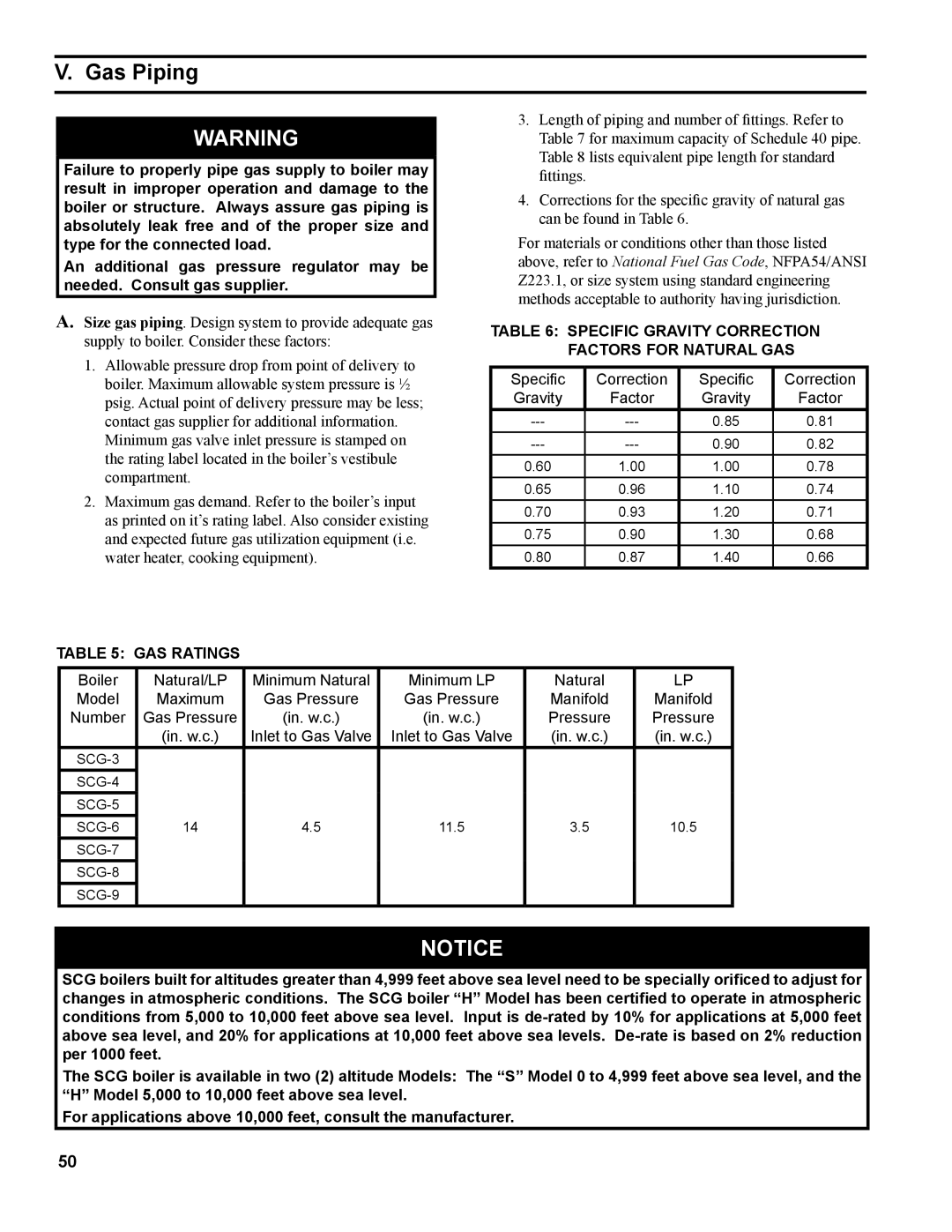
Table 5: Gas Ratings
Boiler | Natural/LP | Minimum Natural | Minimum LP | Natural | LP |
Model | Maximum | Gas Pressure | Gas Pressure | Manifold | Manifold |
Number | Gas Pressure | (in. w.c.) | (in. w.c.) | Pressure | Pressure |
| (in. w.c.) | Inlet to Gas Valve | Inlet to Gas Valve | (in. w.c.) | (in. w.c.) |
|
|
|
|
| |
|
|
|
|
| |
|
|
|
|
| |
14 | 4.5 | 11.5 | 3.5 | 10.5 | |
|
|
|
|
| |
|
|
|
|
| |
|
|
|
|
|
NOTICE![]()
SCG boilers built for altitudes greater than 4,999 feet above sea level need to be specially orificed to adjust for changes in atmospheric conditions. The SCG boiler “H” Model has been certified to operate in atmospheric conditions from 5,000 to 10,000 feet above sea level. Input is
The SCG boiler is available in two (2) altitude Models: The “S” Model 0 to 4,999 feet above sea level, and the “H” Model 5,000 to 10,000 feet above sea level.
For applications above 10,000 feet, consult the manufacturer.
50