III. Venting / Air Intake Piping
WARNING
Do not use this boiler with galvanized, Type 304 or Type 316 stainless steel, non metallic or any other non
Do not use a barometric damper or drafthood with this appliance.
Do not use vent dampers with this boiler.
Moisture and ice may form on surfaces around termination. To prevent deterioration, surfaces should be in good repair (sealed, painted, etc.).
This appliance needs fresh air for safe operation and must be installed so there are provisions for adequate combustion and ventilation air.
Do not reduce size of air intake pipe.
Read, understand and follow combustion air instruction restrictions contained in the
Do not operate appliance where gasoline or other flammable vapors or liquids, or sources of hydro- carbons (i.e. bleaches, cleaners, chemicals, sprays, paint removers, fabric softeners, etc.) are used, stored and/or present in the air.
When installing vent pipe through chimney, no other appliance can be vented into the chimney.
Do not exceed maximum vent/air intake lengths. Refer to Table 4.
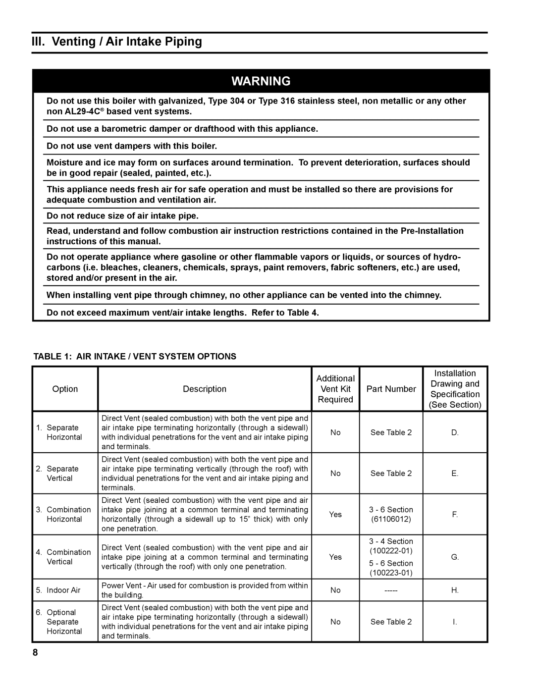
Table 1: Air Intake / Vent System Options
|
|
| Additional |
| Installation | |
|
|
|
| Drawing and | ||
| Option | Description | Vent Kit | Part Number | ||
| Specification | |||||
|
|
| Required |
| ||
|
|
|
| (See Section) | ||
|
|
|
|
| ||
|
| Direct Vent (sealed combustion) with both the vent pipe and |
|
|
| |
1. | Separate | air intake pipe terminating horizontally (through a sidewall) | No | See Table 2 | D. | |
| Horizontal | with individual penetrations for the vent and air intake piping | ||||
|
|
|
| |||
|
| and terminals. |
|
|
| |
|
| Direct Vent (sealed combustion) with both the vent pipe and |
|
|
| |
2. | Separate | air intake pipe terminating vertically (through the roof) with | No | See Table 2 | E. | |
| Vertical | individual penetrations for the vent and air intake piping and | ||||
|
|
|
| |||
|
| terminals. |
|
|
| |
|
| Direct Vent (sealed combustion) with the vent pipe and air |
|
|
| |
3. | Combination | intake pipe joining at a common terminal and terminating | Yes | 3 - 6 Section | F. | |
| Horizontal | horizontally (through a sidewall up to 15” thick) with only | (61106012) | |||
|
|
| ||||
|
| one penetration. |
|
|
| |
|
| Direct Vent (sealed combustion) with the vent pipe and air |
| 3 - 4 Section |
| |
4. | Combination |
|
| |||
intake pipe joining at a common terminal and terminating | Yes | G. | ||||
| Vertical | 5 - 6 Section | ||||
| vertically (through the roof) with only one penetration. |
|
| |||
|
|
|
| |||
|
|
|
|
| ||
5. | Indoor Air | Power Vent - Air used for combustion is provided from within | No | H. | ||
the building. | ||||||
|
|
|
|
| ||
6. | Optional | Direct Vent (sealed combustion) with both the vent pipe and |
|
|
| |
air intake pipe terminating horizontally (through a sidewall) |
|
|
| |||
| Separate | No | See Table 2 | I. | ||
| with individual penetrations for the vent and air intake piping | |||||
| Horizontal |
|
|
| ||
| and terminals. |
|
|
| ||
|
|
|
|
|