Manuals
/
Bush Hog
/
Lawn and Garden
/
Lawn Mower
Bush Hog
HM2007, HM2008, HM2009
manual
Bush HOG
Models:
HM2009
HM2007
HM2008
1
1
62
62
Download
62 pages
14.31 Kb
1
2
3
4
5
6
7
8
Conversion Chart
Safety Signs Signal Words
Maintenance
Assembly Instructions
Important Safety Precautions
Safety
Page 1
Image 1
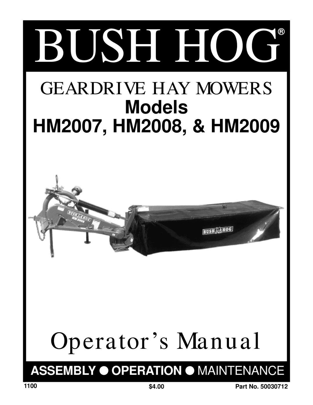
BUSH HOG
®
GEARDRIVE HAY MOWERS
Models
HM2007, HM2008, & HM2009
Operator’s Manual
ASSEMBLY
●
OPERATION
● MAINTENANCE
1100
$4.00
Part No. 50030712
Page 1
Page 2
Page 1
Image 1
Page 1
Page 2
Contents
Bush HOG
Congratulations
HAY Mower
Bush HOG
Dealer Preparation Check List
Safety Signs Signal Words
Safety Alert Symbol
Important Safety Precautions
Osha Regulations
This Act Seeks
Child Labor Under 16 Years Old
Models HM2007 HM2008 HM2009
Generally about supplementary equipment
Model HM2007 Model HM2008 Model HM2009
Machine Identification
Kg / lb
General Safety Instructions
Safety
Page
Page
Model Kg lb HM2007 415 HM2008 440 HM2009 465
Safety instructions during crane lift
Page
New Machine be careful
HM2009
Do the following before coupling the machine to the tractor
Preparation For Use
Model Color
Clip Pin Pawl Remove Clip Pin and Rotate Pawl
Fitting of the suspension
Mounting coupling
Min mm
Shortening of the shaft
PTO shaft
Checking of PTO shaft length
Model HM2008 11mm 7/16
Model HM2007 13mm 1/2
Model HM2009 8 mm 5/16
Stabilizer
Height of the suspension
Lifting height
If the distance C is too big, raise the lift arm at D
Page
Transport
Transport Unhitching
Unhitching
80 ± 95 ± 60 ft./lbs 70 ft./lbs
Operate with safety note the following
Maintenance
Knives cutting discs
Hole In Front Belt Guard
Lubrication generally
Belts
Oil Filler Plug
Oil bevel gearbox
Oil cutterbar
Oil level Plug D
Swath Roller
Right-hand & Left-hand swath rollers
Optional equipment
Right-hand & Left-hand swath boards
Hillside Kit As Seen From Below
Optional high skid
Optional hillside kit
Flat Blades
Throwing wings
Special flat knives
Left cone
2.8 mm
Directions for repair
Important, when fitting the gear to the machine
Hydraulic lifting cylinder
Bevel gearbox
Page
Collar bearings illustration
Cutterbar
Fixing of collar bearing ilustration
Synchronizing illustration
Problem Possible Cause Correction
Problem/Fault Analysis and Corrections
Winter storage
Lubricants
Conversion Chart
Torque Value
Assembly Instructions
Support Leg U Bracket
16-40 mm
Twisted Strut
12 40 mm Plow Bolt 12 35mm Plow Bolt
Model HM2009 Model HM2008 Model HM2007
59 ft./lbs
Working Direction Gearbox
Gearbox
Working Direction
10 35 mm 10 30 mm
10 30 mm 30 -10.5 3 mm
10 -30 mm 30 10.5 3 mm
Optional Equipment
Safety Decals
Page
Page
Bush HOG
Top
Page
Image
Contents