Cabletron Systems 3H02-04, 3H08-04 manual Connectors, LEDs, 1.3.3 Offline Button

Models: 3H08-04 3H02-04

1 42
Download 42 pages 24.72 Kb
Page 12
Image 12
1.3.1 Connectors

Chapter 1: Introduction

1.3.1 Connectors

The 3H02-04 includes four 8-pin RJ45 receptacle connectors that you can attach directly to the network by using unshielded twisted-pair (UTP) cabling. The ATX power supply provides the power for the module.

NOTE

An internal receive/transmit pair crossover is provided in the second connector on each port. This means that when either a station or server is directly attached to a 3H02-04 port, you can choose to use either straight-through or crossover cabling. For more cabling and crossover information, see Appendix B.

1.3.2 LEDs

The 3H02-04 contains a total of 14 green LEDs labeled LINK, RX, and TX for each segment, plus PROC and PWR for the module. The LEDs are described in Chapter 5 of this manual.

1.3.3 Offline Button

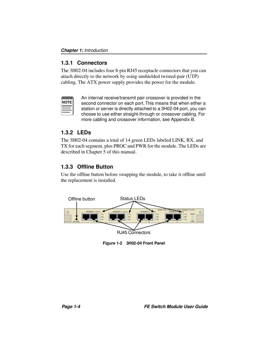
Use the offline button before swapping the module, to take it offline until the replacement is installed.

Offline button

Status LEDs


SEGMENT 1


QUAD FAST ETHERNET / 802.3 100BASE-TX (UTP)


SEGMENT 2

SEGMENT 3

SEGMENT 4


TX


TX

TX

TX

PROC


RX


RX

RX

RX


LK


LK

LK

LK


OFFLINE

X

X

X

X


PWR

RJ45 Connectors

Figure 1-2 3H02-04 Front Panel

Page 1-4

FE Switch Module User Guide

Page 12
Image 12
Cabletron Systems 3H02-04, 3H08-04 manual Connectors, LEDs, 1.3.3 Offline Button