Cabletron Systems 3H02-04, 3H08-04 B.3 FAST ETHERNET PIN ASSIGNMENTS B.3.1 About RJ45 Connectors

Models: 3H08-04 3H02-04

1 42
Download 42 pages 24.72 Kb
Page 38
Image 38
B.3 FAST ETHERNET PIN ASSIGNMENTS

Appendix B: Cables

NOTE

You can also choose to use 50/125, 80/125, or 100/140 micron core multimedia fiber; however, data in the table above applies only to the 62.5/125 type.

B.3 FAST ETHERNET PIN ASSIGNMENTS

B.3.1 About RJ45 Connectors

If you’re connecting a 3H02-04 to another device, it’s required that you use only RJ45 connectors on the cabling. An Ethernet twisted-pair link segment requires two pairs of wires. Each wire pair is identified by solid and striped colored wires. For example, one wire in the pair might be red and the other wire, red with white stripes.

NOTE

You must connect each wire pair to the RJ45 connectors in a certain orientation (See “Crossover Wiring for the 3H02-04” on page B-3 for an explanation).

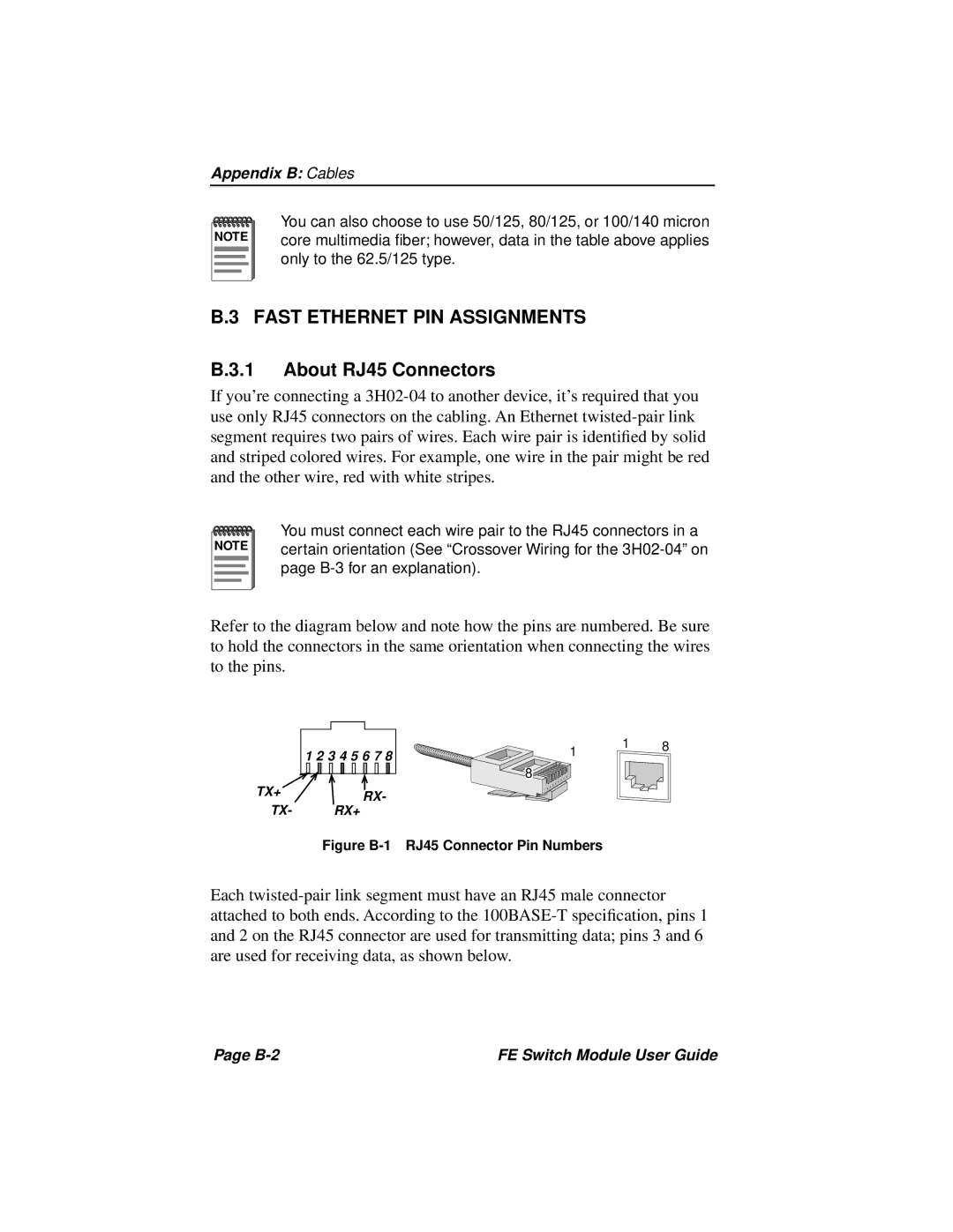
Refer to the diagram below and note how the pins are numbered. Be sure to hold the connectors in the same orientation when connecting the wires to the pins.

1 2 3 4 5 6 7 8

TX+ Figure B-1 RJ45 Connector Pin NumbersManual background RX-

TX- RX+

1 1 8

8

Figure B-1 RJ45 Connector Pin Numbers

Each twisted-pair link segment must have an RJ45 male connector attached to both ends. According to the 100BASE-T specification, pins 1 and 2 on the RJ45 connector are used for transmitting data; pins 3 and 6 are used for receiving data, as shown below.

Page B-2

FE Switch Module User Guide

Page 38
Image 38
Cabletron Systems 3H02-04, 3H08-04 manual B.3 FAST ETHERNET PIN ASSIGNMENTS B.3.1 About RJ45 Connectors