Appendix B: ATM Overview
When a message is sent out by a user:
•It passes from the highest layer in the model, the Applications Layer, down to the lowest layer, the Physical Layer.
•The Physical Layer physically transmits the message over a particular media.
When this message reaches its destination:
•It passes upward, in the reverse order, from the Physical Layer to the Applications Layer.
•Each layer strips off the information that was added by its counterpart on the transmitting end. What you inevitably end up with is the same thing you started out with
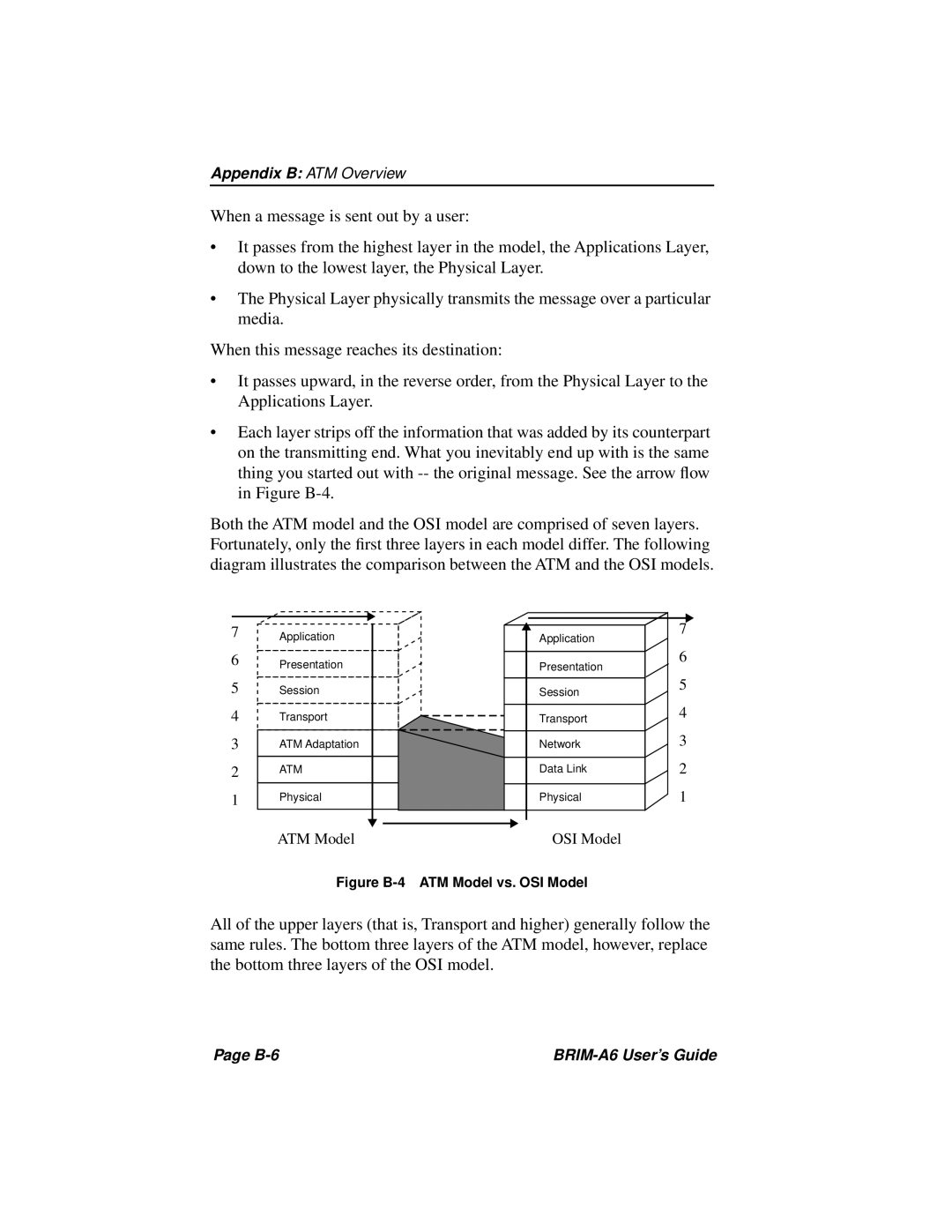
Both the ATM model and the OSI model are comprised of seven layers. Fortunately, only the first three layers in each model differ. The following diagram illustrates the comparison between the ATM and the OSI models.
7
6
5
4
3
2
1
Application
Presentation
Session
Transport
ATM Adaptation
ATM
Physical
ATM Model
Application
Presentation
Session
Transport
Network
Data Link
Physical
OSI Model
7
6
5
4
3
2
1
Figure B-4 ATM Model vs. OSI Model
All of the upper layers (that is, Transport and higher) generally follow the same rules. The bottom three layers of the ATM model, however, replace the bottom three layers of the OSI model.
Page |
|