Chapter 2: Installation
11.Secure the
Ensure that the chassis cover is in place before reconnecting the power cord.
12.Reattach the chassis cover to the standalone device, reconnect the power cord, and reconnect the standalone device to the network.
2.3CONNECTING TO THE NETWORK
The
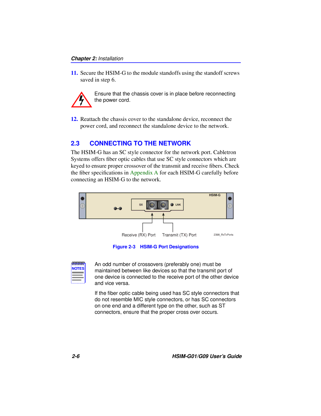
SX
LNK
NOTES |
Receive (RX) Port | Transmit (TX) Port | 2398_RxTxPorts |
Figure 2-3 HSIM-G Port Designations
An odd number of crossovers (preferably one) must be maintained between like devices so that the transmit port of one device is connected to the receive port of the other device and vice versa.
If the fiber optic cable being used has SC style connectors that do not resemble MIC style connectors, or has SC connectors on one end and a different type on the other, such as ST connectors, ensure that the proper cross over occurs.
|