Table 6 Powerflex 755 Fault Code Descriptions and Corrective Actions (cont)

VFD


FAULT

ICVC


CODE


FAULT

FAULT TYPE

DESCRIPTION

CORRECTIVE ACTION

ON VFD

STATE


HIST


SCREEN


168


HeatSinkUnder-

Heatsink temperature sensor is reporting a value

Check heat sink temperature sensor. Check heat

206

below -18.7 C (-1.66 F) or the sensor feedback

Tmp

sink temperature.


circuit is open.


210

206

HW En Jumper

See VFD Fault Code 15

See VFD Fault Code 15

Out


211

206

Safety Brd Fault

See VFD Fault Code 15

See VFD Fault Code 15

213

206

Safety Jumper In

See VFD Fault Code 15

See VFD Fault Code 15

291

206

HSFan Lifwe

See VFD Fault Code 15

See VFD Fault Code 15

292

206

InFan Life

See VFD Fault Code 15

See VFD Fault Code 15

293

206

MtrBrg Life

See VFD Fault Code 15

See VFD Fault Code 15

294

206

MtrBrg Lube

See VFD Fault Code 15

See VFD Fault Code 15

295

206

MachBrg life

See VFD Fault Code 15

See VFD Fault Code 15

296

206

MachBrg Lube

See VFD Fault Code 15

See VFD Fault Code 15

315

206

Excess Psn Error

See VFD Fault Code 15

See VFD Fault Code 15

316

206

Node Fault Error

See VFD Fault Code 15

See VFD Fault Code 15

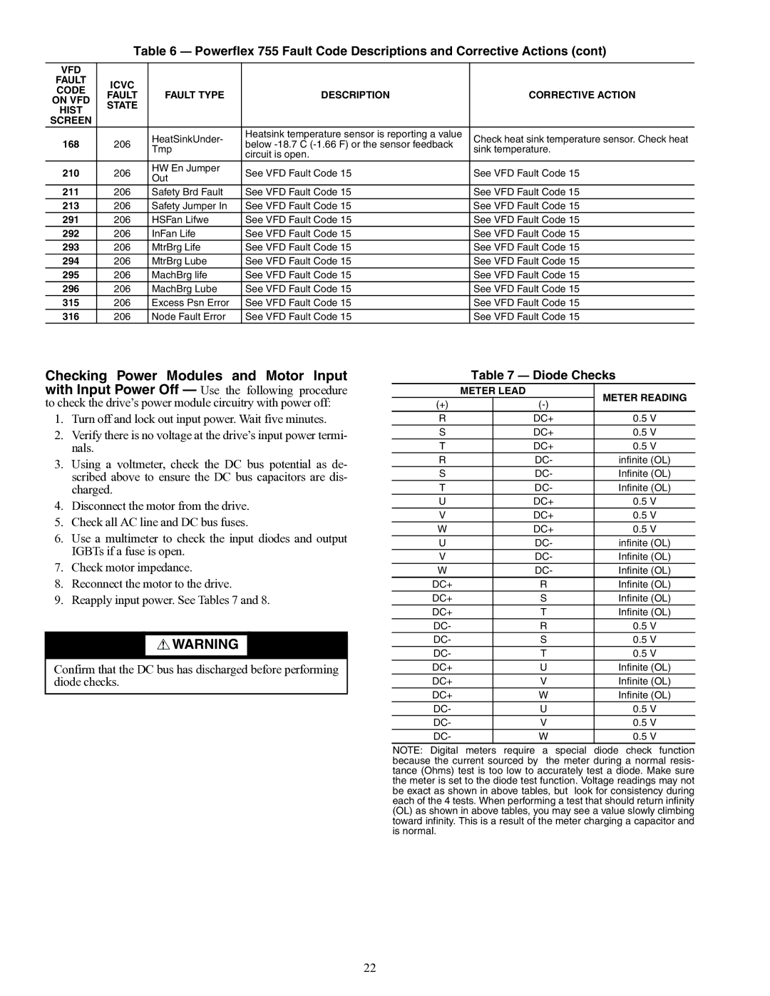
Checking Power Modules and Motor Input with Input Power Off — Use the following procedure to check the drive’s power module circuitry with power off:

1.Turn off and lock out input power. Wait five minutes.

2.Verify there is no voltage at the drive’s input power termi- nals.

3.Using a voltmeter, check the DC bus potential as de- scribed above to ensure the DC bus capacitors are dis- charged.

4.Disconnect the motor from the drive.

5.Check all AC line and DC bus fuses.

6.Use a multimeter to check the input diodes and output IGBTs if a fuse is open.

7.Check motor impedance.

8.Reconnect the motor to the drive.

9.Reapply input power. See Tables 7 and 8.

WARNING

Confirm that the DC bus has discharged before performing diode checks.

Table 7 Diode Checks


METER LEAD

METER READING

(+)


(-)


R


DC+

0.5 V

S


DC+

0.5 V

T


DC+

0.5 V

R


DC-

infinite (OL)

S


DC-

Infinite (OL)

T


DC-

Infinite (OL)

U


DC+

0.5 V

V


DC+

0.5 V

W


DC+

0.5 V

U


DC-

infinite (OL)

V


DC-

Infinite (OL)

W


DC-

Infinite (OL)

DC+


R

Infinite (OL)

DC+


S

Infinite (OL)

DC+


T

Infinite (OL)

DC-


R

0.5 V

DC-


S

0.5 V

DC-


T

0.5 V

DC+


U

Infinite (OL)

DC+


V

Infinite (OL)

DC+


W

Infinite (OL)

DC-


U

0.5 V

DC-


V

0.5 V

DC-


W

0.5 V

NOTE: Digital meters require a special diode check function because the current sourced by the meter during a normal resis- tance (Ohms) test is too low to accurately test a diode. Make sure the meter is set to the diode test function. Voltage readings may not be exact as shown in above tables, but look for consistency during each of the 4 tests. When performing a test that should return infinity (OL) as shown in above tables, you may see a value slowly climbing toward infinity. This is a result of the meter charging a capacitor and is normal.

22

Page 22
Image 22
Carrier 19XRV specifications Diode Checks, Meter Lead Meter Reading

19XRV specifications

The Carrier 19XRV is a cutting-edge rooftop chiller designed to provide reliable and efficient cooling solutions for a wide range of applications, including commercial buildings and industrial facilities. This advanced system integrates the latest technologies and innovative features to ensure optimal performance, energy efficiency, and ease of use.

One of the most prominent features of the 19XRV is its advanced inverter-driven compressor technology. This allows the chiller to adjust its capacity seamlessly based on the building's cooling demand. By varying the speed of the compressor, the 19XRV maximizes energy efficiency and minimizes operational costs, especially during partial load conditions. This capability not only enhances comfort but also contributes to reduced energy consumption, making it a sustainable choice for environmentally conscious users.

In addition to the inverter technology, the 19XRV incorporates a microchannel coil design. This design optimizes heat exchange efficiency and reduces the refrigerant charge, which is an essential factor in lowering greenhouse gas emissions. The microchannel coils also allow for more compact dimensions, making installation easier and maximizing rooftop space usage.

Another significant aspect of the Carrier 19XRV is its robust controls system. Equipped with Carrier’s advanced ComfortLink™ controls, this chiller offers precise monitoring and control over its operation. Users can easily integrate the chiller into building management systems for real-time data access and efficiency analytics. This connectivity ensures that operators can make informed decisions to optimize performance continuously.

The 19XRV also includes features aimed at enhancing reliability and durability. Its structural design incorporates corrosion-resistant materials, allowing the unit to withstand harsh environmental conditions. This reliability translates to lower maintenance requirements and extended equipment lifespan, providing excellent value over time.

Moreover, the chiller is designed for quiet operation, making it suitable for applications where low noise levels are essential. Sound-dampening measures ensure that the 19XRV can be utilized in urban environments or near sensitive areas without causing disturbances.

In conclusion, the Carrier 19XRV is a state-of-the-art rooftop chiller that combines efficiency, technology, and durability. Its inverter-driven compressor, microchannel coil design, advanced controls, and robust construction make it an ideal choice for those looking to maintain comfort while minimizing energy usage and environmental impact. Whether for commercial or industrial applications, the 19XRV stands out as a reliable and innovative cooling solution for the modern age.