19XRV specifications
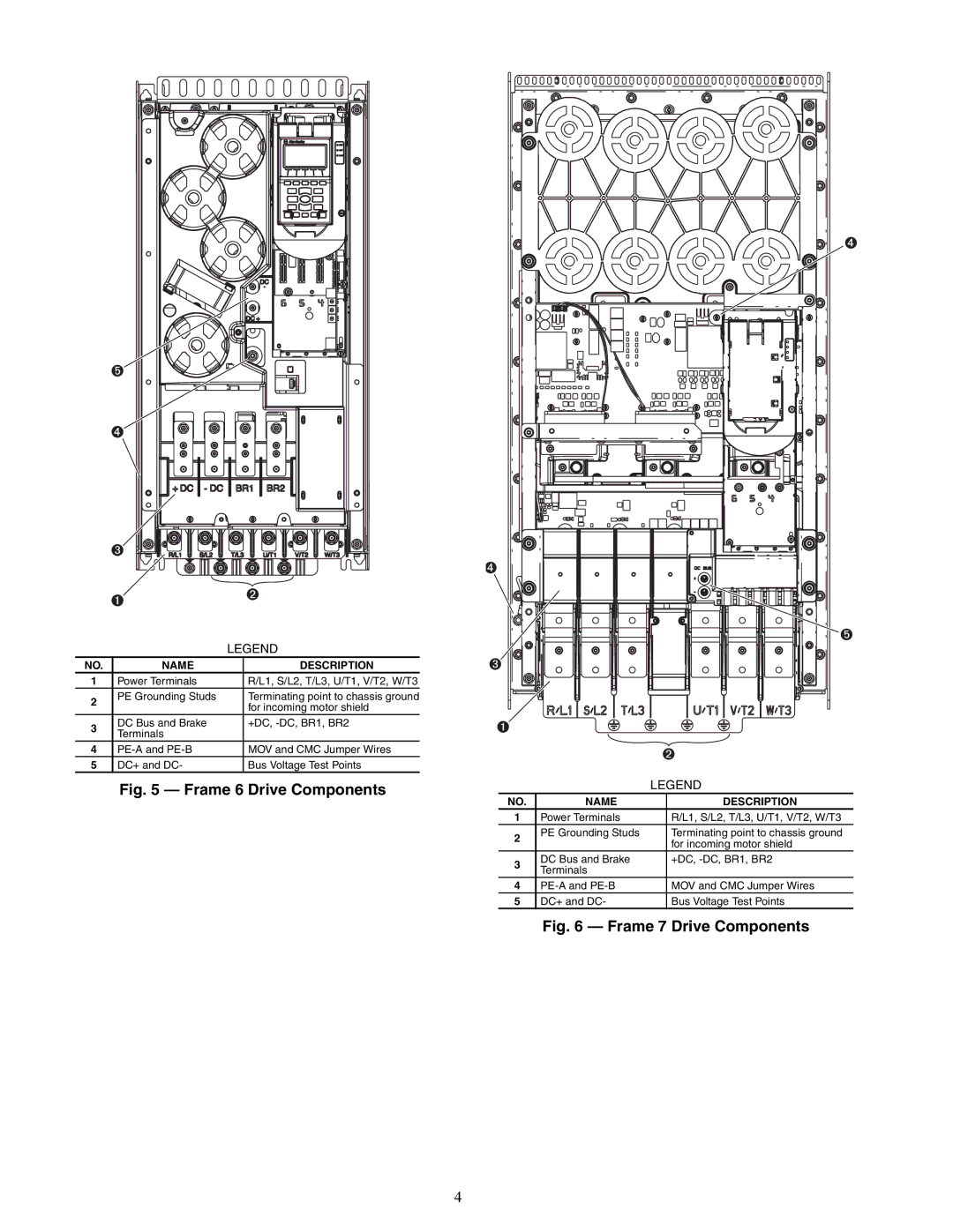
The Carrier 19XRV is a cutting-edge rooftop chiller designed to provide reliable and efficient cooling solutions for a wide range of applications, including commercial buildings and industrial facilities. This advanced system integrates the latest technologies and innovative features to ensure optimal performance, energy efficiency, and ease of use.One of the most prominent features of the 19XRV is its advanced inverter-driven compressor technology. This allows the chiller to adjust its capacity seamlessly based on the building's cooling demand. By varying the speed of the compressor, the 19XRV maximizes energy efficiency and minimizes operational costs, especially during partial load conditions. This capability not only enhances comfort but also contributes to reduced energy consumption, making it a sustainable choice for environmentally conscious users.
In addition to the inverter technology, the 19XRV incorporates a microchannel coil design. This design optimizes heat exchange efficiency and reduces the refrigerant charge, which is an essential factor in lowering greenhouse gas emissions. The microchannel coils also allow for more compact dimensions, making installation easier and maximizing rooftop space usage.
Another significant aspect of the Carrier 19XRV is its robust controls system. Equipped with Carrier’s advanced ComfortLink™ controls, this chiller offers precise monitoring and control over its operation. Users can easily integrate the chiller into building management systems for real-time data access and efficiency analytics. This connectivity ensures that operators can make informed decisions to optimize performance continuously.
The 19XRV also includes features aimed at enhancing reliability and durability. Its structural design incorporates corrosion-resistant materials, allowing the unit to withstand harsh environmental conditions. This reliability translates to lower maintenance requirements and extended equipment lifespan, providing excellent value over time.
Moreover, the chiller is designed for quiet operation, making it suitable for applications where low noise levels are essential. Sound-dampening measures ensure that the 19XRV can be utilized in urban environments or near sensitive areas without causing disturbances.
In conclusion, the Carrier 19XRV is a state-of-the-art rooftop chiller that combines efficiency, technology, and durability. Its inverter-driven compressor, microchannel coil design, advanced controls, and robust construction make it an ideal choice for those looking to maintain comfort while minimizing energy usage and environmental impact. Whether for commercial or industrial applications, the 19XRV stands out as a reliable and innovative cooling solution for the modern age.

