Servicing the Drive

WARNING

To guard against possible personal injury and/or equipment damage:

1.Inspect all lifting hardware for proper attachment be- fore lifting drive.

2.Do not allow any part of the drive or lifting mecha- nism to make contact with electrically charged con- ductors or components.

3.Do not subject the drive to high rates of acceleration or deceleration while transporting to the mounting lo- cation or when lifting.

Do not allow personnel or their limbs directly underneath the drive when it is being lifted and mounted.

1

L1 L2 L3

I


LOCKOUT/TAGOUT


O


2


0V


DC BUS TEST

DC+ DC–


TERMINALS


0V

MULTIMETER

LOCATED INSIDE


ACCESS DOOR

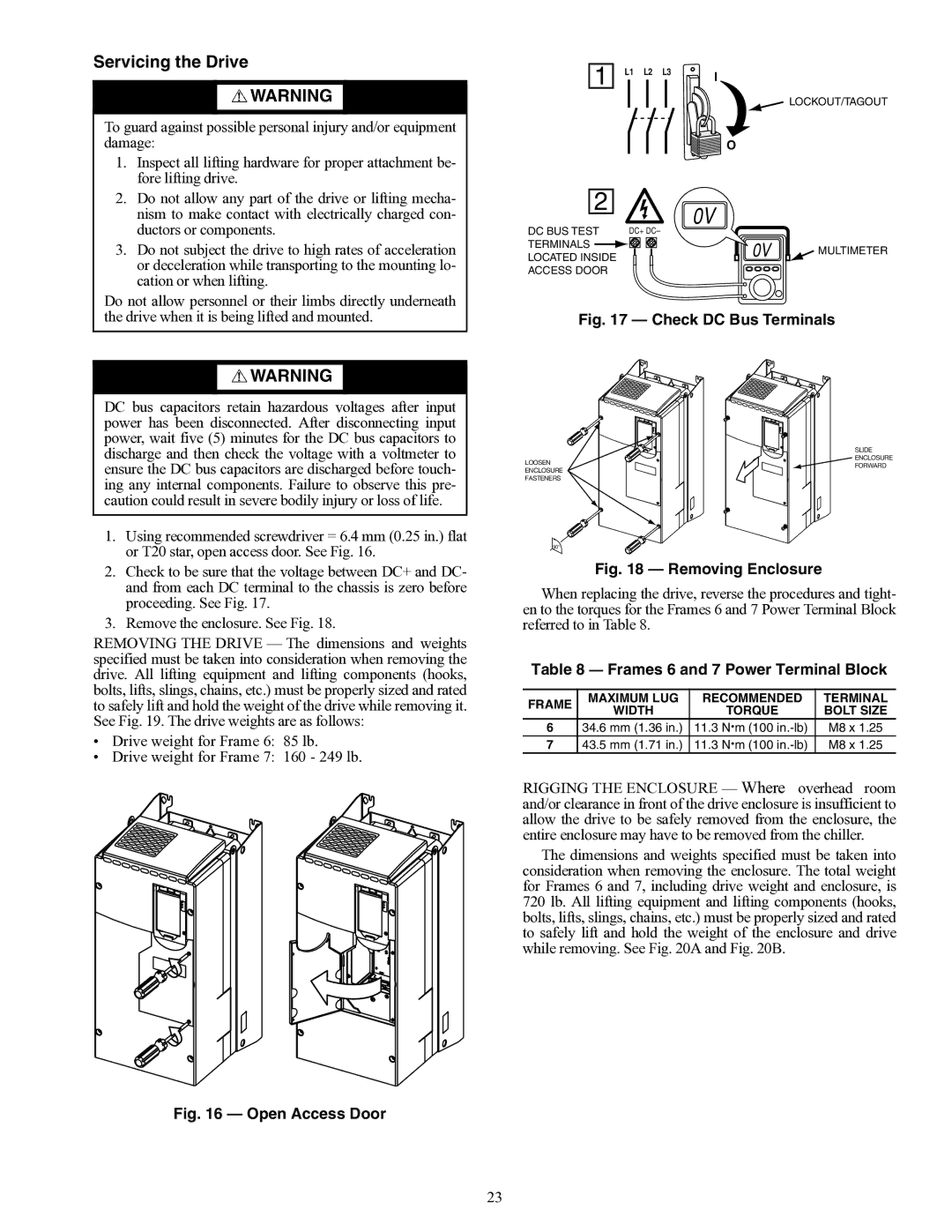
A19-1814Fig. 17 — Check DC Bus Terminals

WARNING

DC bus capacitors retain hazardous voltages after input power has been disconnected. After disconnecting input power, wait five (5) minutes for the DC bus capacitors to discharge and then check the voltage with a voltmeter to ensure the DC bus capacitors are discharged before touch- ing any internal components. Failure to observe this pre- caution could result in severe bodily injury or loss of life.

1.Using recommended screwdriver = 6.4 mm (0.25 in.) flat or T20 star, open access door. See Fig. 16.

2.Check to be sure that the voltage between DC+ and DC- and from each DC terminal to the chassis is zero before proceeding. See Fig. 17.

3.Remove the enclosure. See Fig. 18.

REMOVING THE DRIVE — The dimensions and weights specified must be taken into consideration when removing the drive. All lifting equipment and lifting components (hooks, bolts, lifts, slings, chains, etc.) must be properly sized and rated to safely lift and hold the weight of the drive while removing it. See Fig. 19. The drive weights are as follows:

Drive weight for Frame 6: 85 lb.

Drive weight for Frame 7: 160 - 249 lb.

A19-1831Fig. 16 — Open Access Door


SLIDE

LOOSEN

ENCLOSURE

FORWARD

ENCLOSURE


FASTENERS


90°

A19-1816Fig. 18 — Removing Enclosure

When replacing the drive, reverse the procedures and tight- en to the torques for the Frames 6 and 7 Power Terminal Block referred to in Table 8.

Table 8 Frames 6 and 7 Power Terminal Block

FRAME

MAXIMUM LUG

RECOMMENDED

TERMINAL

WIDTH

TORQUE

BOLT SIZE


6

34.6 mm (1.36 in.)

11.3 N·m (100 in.-lb)

M8 x 1.25

7

43.5 mm (1.71 in.)

11.3 N·m (100 in.-lb)

M8 x 1.25

RIGGING THE ENCLOSURE — Where overhead room and/or clearance in front of the drive enclosure is insufficient to allow the drive to be safely removed from the enclosure, the entire enclosure may have to be removed from the chiller.

The dimensions and weights specified must be taken into consideration when removing the enclosure. The total weight for Frames 6 and 7, including drive weight and enclosure, is 720 lb. All lifting equipment and lifting components (hooks, bolts, lifts, slings, chains, etc.) must be properly sized and rated to safely lift and hold the weight of the enclosure and drive while removing. See Fig. 20A and Fig. 20B.

23

Page 23
Image 23
Carrier 19XRV A19-1814Fig Check DC Bus Terminals, A19-1831Fig Open Access Door, A19-1816Fig Removing Enclosure

19XRV specifications

The Carrier 19XRV is a cutting-edge rooftop chiller designed to provide reliable and efficient cooling solutions for a wide range of applications, including commercial buildings and industrial facilities. This advanced system integrates the latest technologies and innovative features to ensure optimal performance, energy efficiency, and ease of use.

One of the most prominent features of the 19XRV is its advanced inverter-driven compressor technology. This allows the chiller to adjust its capacity seamlessly based on the building's cooling demand. By varying the speed of the compressor, the 19XRV maximizes energy efficiency and minimizes operational costs, especially during partial load conditions. This capability not only enhances comfort but also contributes to reduced energy consumption, making it a sustainable choice for environmentally conscious users.

In addition to the inverter technology, the 19XRV incorporates a microchannel coil design. This design optimizes heat exchange efficiency and reduces the refrigerant charge, which is an essential factor in lowering greenhouse gas emissions. The microchannel coils also allow for more compact dimensions, making installation easier and maximizing rooftop space usage.

Another significant aspect of the Carrier 19XRV is its robust controls system. Equipped with Carrier’s advanced ComfortLink™ controls, this chiller offers precise monitoring and control over its operation. Users can easily integrate the chiller into building management systems for real-time data access and efficiency analytics. This connectivity ensures that operators can make informed decisions to optimize performance continuously.

The 19XRV also includes features aimed at enhancing reliability and durability. Its structural design incorporates corrosion-resistant materials, allowing the unit to withstand harsh environmental conditions. This reliability translates to lower maintenance requirements and extended equipment lifespan, providing excellent value over time.

Moreover, the chiller is designed for quiet operation, making it suitable for applications where low noise levels are essential. Sound-dampening measures ensure that the 19XRV can be utilized in urban environments or near sensitive areas without causing disturbances.

In conclusion, the Carrier 19XRV is a state-of-the-art rooftop chiller that combines efficiency, technology, and durability. Its inverter-driven compressor, microchannel coil design, advanced controls, and robust construction make it an ideal choice for those looking to maintain comfort while minimizing energy usage and environmental impact. Whether for commercial or industrial applications, the 19XRV stands out as a reliable and innovative cooling solution for the modern age.