Carrier 30GK manual Description of the Information menu

Models: 30GK

1 36
Download 36 pages 54.78 Kb
Page 15
Image 15
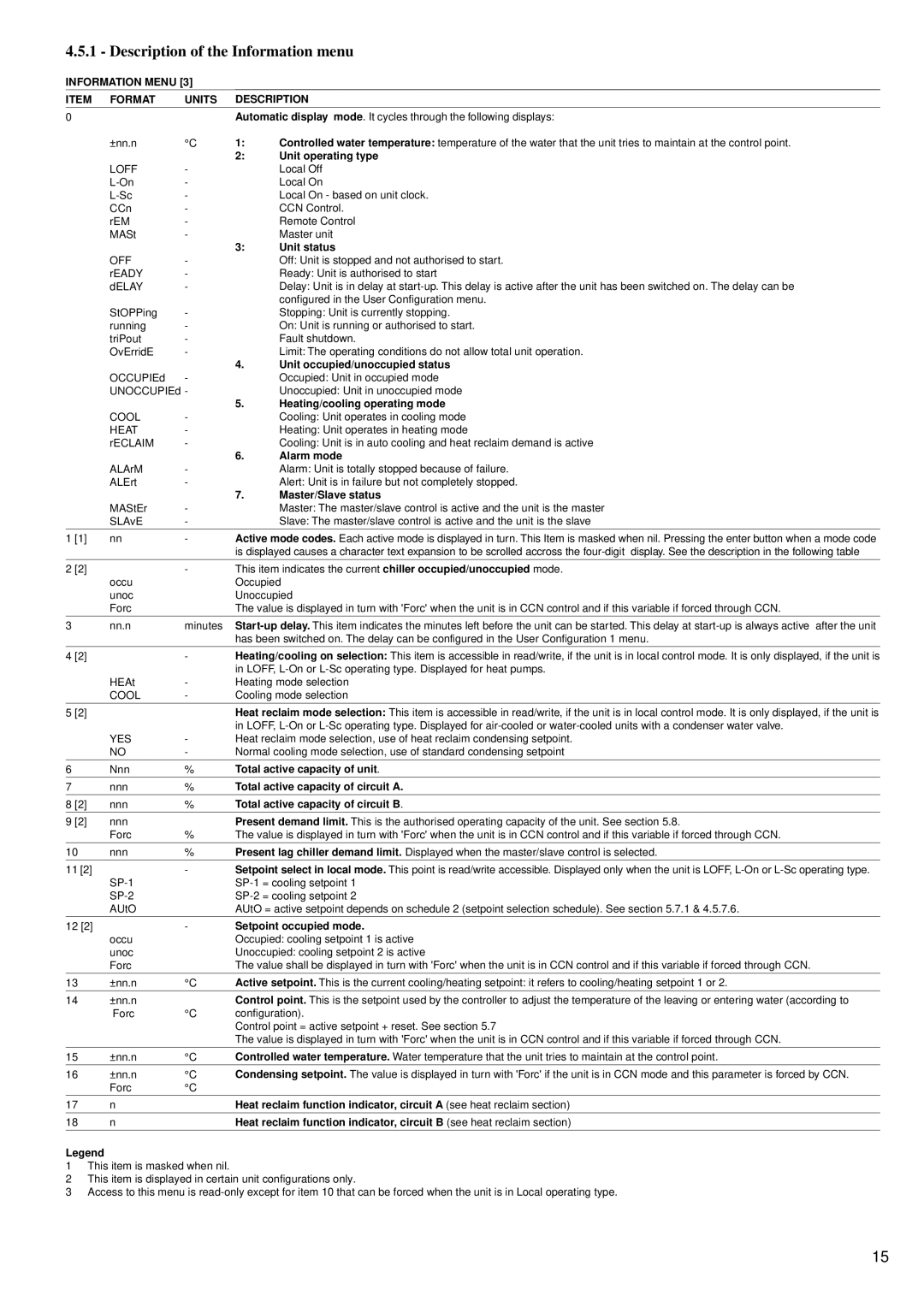
4.5.1 - Description of the Information menu

4.5.1 - Description of the Information menu

INFORMATION MENU [3]

ITEM

FORMAT

UNITS

DESCRIPTION

0


Automatic display mode. It cycles through the following displays:


±nn.n

°C

1:

Controlled water temperature: temperature of the water that the unit tries to maintain at the control point.


2:

Unit operating type


LOFF

-


Local Off


L-On

-


Local On


L-Sc

-


Local On - based on unit clock.


CCn

-


CCN Control.


rEM

-


Remote Control


MASt

-


Master unit


3:

Unit status


OFF

-


Off: Unit is stopped and not authorised to start.


rEADY

-


Ready: Unit is authorised to start


dELAY

-


Delay: Unit is in delay at start-up. This delay is active after the unit has been switched on. The delay can be


configured in the User Configuration menu.


StOPPing

-


Stopping: Unit is currently stopping.


running

-


On: Unit is running or authorised to start.


triPout

-


Fault shutdown.


OvErridE

-


Limit: The operating conditions do not allow total unit operation.


4.

Unit occupied/unoccupied status


OCCUPIEd

-


Occupied: Unit in occupied mode


UNOCCUPIEd -


Unoccupied: Unit in unoccupied mode


5.

Heating/cooling operating mode


COOL

-


Cooling: Unit operates in cooling mode


HEAT

-


Heating: Unit operates in heating mode


rECLAIM

-


Cooling: Unit is in auto cooling and heat reclaim demand is active


6.

Alarm mode


ALArM

-


Alarm: Unit is totally stopped because of failure.


ALErt

-


Alert: Unit is in failure but not completely stopped.


7.

Master/Slave status


MAStEr

-


Master: The master/slave control is active and the unit is the master


SLAvE

-


Slave: The master/slave control is active and the unit is the slave


1 [1]

nn

-

Active mode codes. Each active mode is displayed in turn. This Item is masked when nil. Pressing the enter button when a mode code


is displayed causes a character text expansion to be scrolled accross the four-digit display. See the description in the following table


2 [2]


-

This item indicates the current chiller occupied/unoccupied mode.


occu


Occupied


unoc


Unoccupied


Forc


The value is displayed in turn with 'Forc' when the unit is in CCN control and if this variable if forced through CCN.

3

nn.n

minutes

Start-up delay. This item indicates the minutes left before the unit can be started. This delay at start-up is always active after the unit


has been switched on. The delay can be configured in the User Configuration 1 menu.


4 [2]


-

Heating/cooling on selection: This item is accessible in read/write, if the unit is in local control mode. It is only displayed, if the unit is


in LOFF, L-On or L-Sc operating type. Displayed for heat pumps.


HEAt

-

Heating mode selection


COOL

-

Cooling mode selection

5 [2]


Heat reclaim mode selection: This item is accessible in read/write, if the unit is in local control mode. It is only displayed, if the unit is


in LOFF, L-On or L-Sc operating type. Displayed for air-cooled or water-cooled units with a condenser water valve.


YES

-

Heat reclaim mode selection, use of heat reclaim condensing setpoint.


NO

-

Normal cooling mode selection, use of standard condensing setpoint


6

Nnn

%

Total active capacity of unit.


7

nnn

%

Total active capacity of circuit A.


8 [2]

nnn

%

Total active capacity of circuit B.


9 [2]

nnn


Present demand limit. This is the authorised operating capacity of the unit. See section 5.8.


Forc

%

The value is displayed in turn with 'Forc' when the unit is in CCN control and if this variable if forced through CCN.

10

nnn

%

Present lag chiller demand limit. Displayed when the master/slave control is selected.

11 [2]


-

Setpoint select in local mode. This point is read/write accessible. Displayed only when the unit is LOFF, L-On or L-Sc operating type.


SP-1


SP-1 = cooling setpoint 1


SP-2


SP-2 = cooling setpoint 2


AUtO


AUtO = active setpoint depends on schedule 2 (setpoint selection schedule). See section 5.7.1 & 4.5.7.6.


12 [2]


-

Setpoint occupied mode.


occu


Occupied: cooling setpoint 1 is active


unoc


Unoccupied: cooling setpoint 2 is active


Forc


The value shall be displayed in turn with 'Forc' when the unit is in CCN control and if this variable if forced through CCN.

13

±nn.n

°C

Active setpoint. This is the current cooling/heating setpoint: it refers to cooling/heating setpoint 1 or 2.

14

±nn.n


Control point. This is the setpoint used by the controller to adjust the temperature of the leaving or entering water (according to


Forc

°C

configuration).


Control point = active setpoint + reset. See section 5.7


The value is displayed in turn with 'Forc' when the unit is in CCN control and if this variable if forced through CCN.


15

±nn.n

°C

Controlled water temperature. Water temperature that the unit tries to maintain at the control point.


16

±nn.n

°C

Condensing setpoint. The value is displayed in turn with 'Forc' if the unit is in CCN mode and this parameter is forced by CCN.


Forc

°C


17

n


Heat reclaim function indicator, circuit A (see heat reclaim section)

18

n


Heat reclaim function indicator, circuit B (see heat reclaim section)

Legend

1This item is masked when nil.

2This item is displayed in certain unit configurations only.

3Access to this menu is read-only except for item 10 that can be forced when the unit is in Local operating type.

15

Page 15
Image 15
Carrier 30GK manual Description of the Information menu