30GK specifications
The Carrier 30GK is a prominent chiller model known for its efficiency and reliability in various commercial and industrial applications. Offering a blend of advanced technology and robust design, the 30GK series caters to diverse cooling needs while maintaining energy efficiency and low operational costs.One of the standout features of the 30GK is its use of the latest scroll compressor technology. This contributes to its efficient performance, enabling the chiller to operate at optimal levels while minimizing energy consumption. The scroll compressor is known for its quiet operation, which reduces noise pollution, making it an ideal choice for buildings located in noise-sensitive environments.
The 30GK chiller series is equipped with microchannel coil technology, which allows for improved heat exchange efficiency. The microchannel design uses a compact coil structure that enhances refrigerant flow and reduces refrigerant volume, leading to a smaller footprint compared to traditional coil designs. This innovative design not only saves space but also improves the chiller's overall performance.
Another notable characteristic of the Carrier 30GK is its environmental consciousness. The chiller operates using environmentally friendly refrigerants, aligning with modern regulations and sustainability goals. Its design incorporates energy-efficient components that contribute to significant reductions in greenhouse gas emissions, making it suitable for environmentally responsible projects.
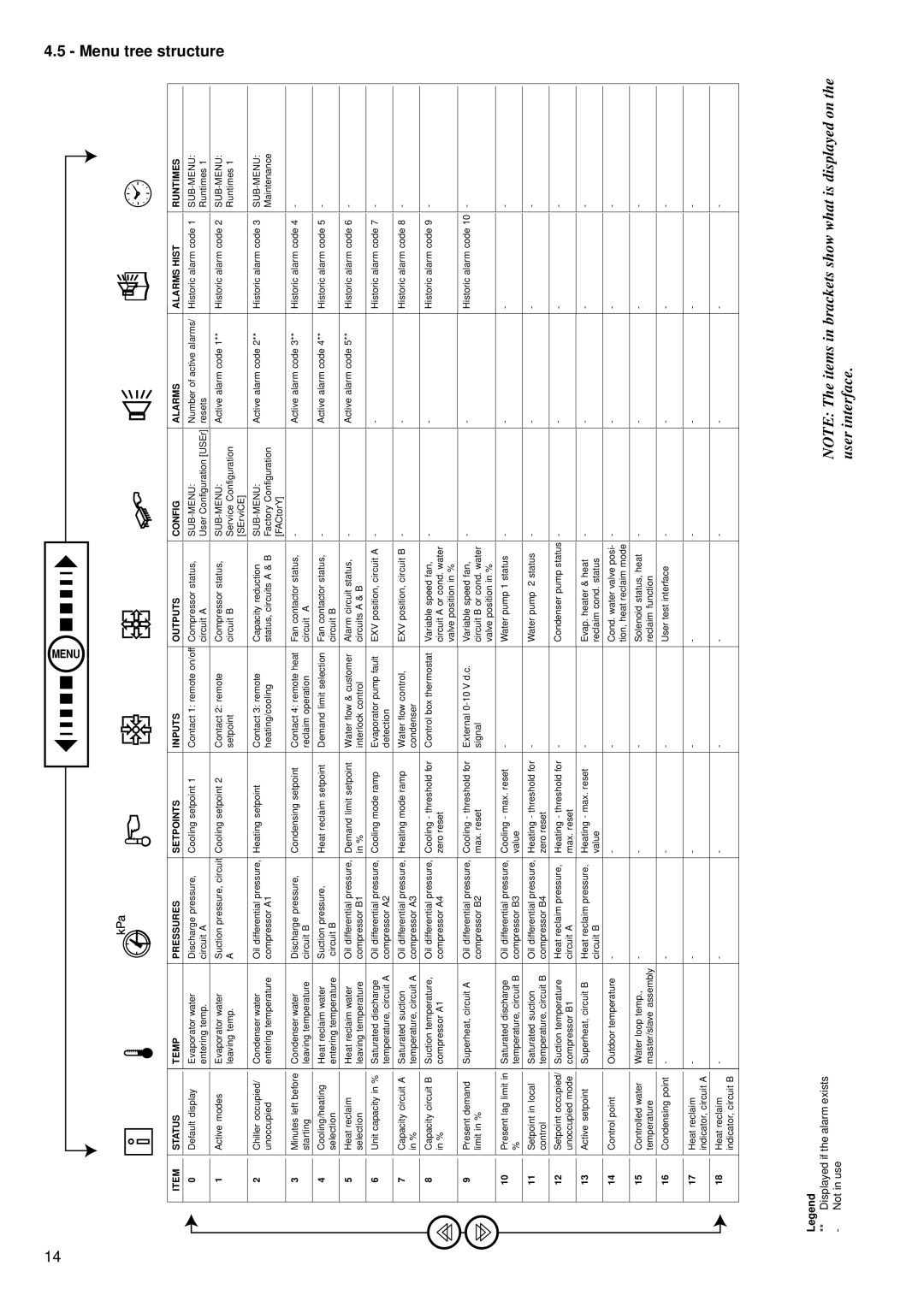
Moreover, the 30GK is designed for easy serviceability, with accessible components that simplify maintenance. This feature is particularly important for facility managers seeking to minimize downtime and keep maintenance costs low. The chiller also includes advanced monitoring and control systems, which enable real-time performance tracking and diagnostics, enhancing operational efficiency.
In terms of performance, the 30GK chiller is known for its wide capacity range, making it versatile for various applications. Whether for commercial spaces, industrial processes, or large buildings, the 30GK can meet the cooling demands reliably.
Overall, the Carrier 30GK chiller represents a perfect balance of cutting-edge technology, energy efficiency, and sustainability. Its features make it a leading choice in the market, suited for those looking to invest in high-quality and dependable cooling solutions.

