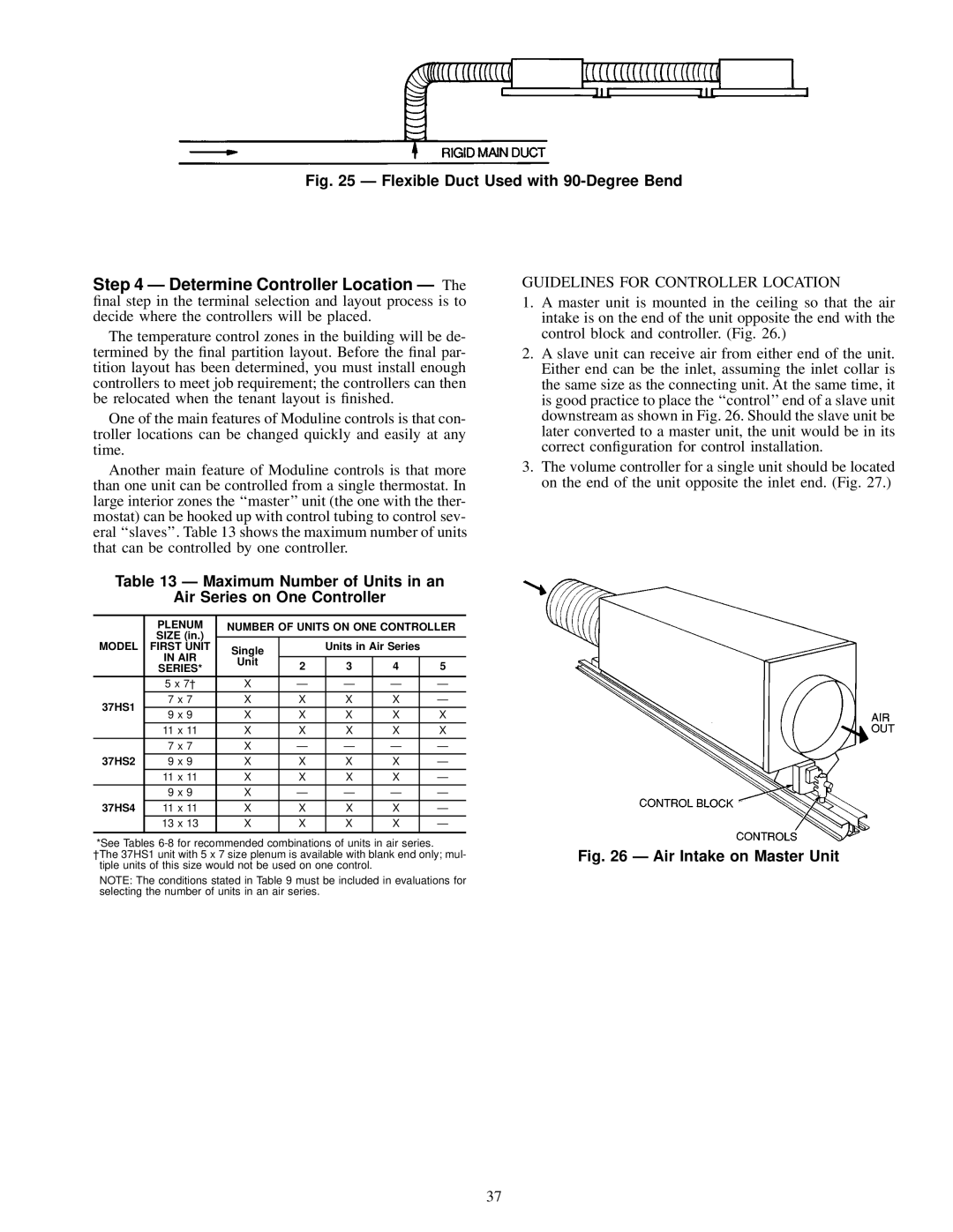
37HS specifications
The Carrier 37HS is a cutting-edge heating, ventilation, and air conditioning (HVAC) solution designed to deliver exceptional performance and energy efficiency for residential and commercial applications. This unit is particularly favored for its advanced features and reliable operation, making it a popular choice among homeowners and building managers alike.One of the standout characteristics of the Carrier 37HS is its high Seasonal Energy Efficiency Ratio (SEER), which indicates its ability to provide effective cooling while minimizing energy consumption. This makes it not only cost-effective but also an environmentally-friendly choice, helping to reduce the overall carbon footprint. The unit is equipped with state-of-the-art inverter technology, which allows it to adjust its cooling capacity to match the current demand, thus enhancing comfort while optimizing energy use.
The Carrier 37HS incorporates a high-efficiency scroll compressor that operates quietly and efficiently. This technology enhances the unit's reliability and longer service life while ensuring minimal noise levels during operation, making it suitable for residential settings where tranquility is paramount.
A significant feature of the 37HS is its variable-speed fan system, which enables gradual adjustments in airflow to maintain a consistent and comfortable indoor environment. This not only contributes to enhanced comfort but also reduces wear and tear on the system, further extending its longevity.
Moreover, the Carrier 37HS is designed with advanced air filtration capabilities, utilizing multi-stage filters that capture airborne particles, allergens, and pollutants. This results in improved indoor air quality, making it an ideal choice for those with allergies or respiratory issues.
The unit also boasts user-friendly smart controls, allowing homeowners to monitor and adjust settings remotely via a smartphone app. This feature adds convenience and assists in energy management, ensuring that users can optimize their HVAC system even when they are away from home.
In summary, the Carrier 37HS stands out for its exceptional energy efficiency, quiet operation, advanced technology, superior air filtration, and modern smart controls. These features collectively make it a prime solution for those seeking a reliable HVAC system that delivers both comfort and savings, while also contributing positively to environmental sustainability. Whether for a residential setting or a commercial establishment, the Carrier 37HS is engineered to meet a variety of climate control needs with excellence.

