a50-8452
Complete C
![]()
![]()
![]() SEE NOTE 9
SEE NOTE 9
Complete C
|
| LEGEND |
|
|
|
|
| ||||
AL | — | Alarm Relay Contacts |
|
|
|
| Relay/Contactor Coil | ||||
BM | — | Blower Motor |
|
|
|
| |||||
BR | — | Blower Relay |
|
|
|
|
| ||||
CAP | — | Capacitor |
|
|
|
| Solenoid Coil | ||||
CB | — | Circuit Breaker |
|
|
|
|
| ||||
CO | — | Sensor, Condensate Overflow |
|
|
|
| Thermistor | ||||
CR | — | Compressor Relay |
|
|
|
|
| ||||
DM | — | Damper Motor |
|
|
|
|
|
|
| Circuit Breaker | |
|
|
|
|
| |||||||
FP1 | — | Sensor, Water Coil Freeze Protection |
|
|
|
|
|
| Relay | ||
FP2 | — | Sensor, Air Coil Freeze Protection |
|
|
|
|
|
| |||
|
|
|
|
|
| ||||||
HP | — |
|
|
|
| ||||||
JW1 | — | Jumper Wire for Alarm |
|
|
|
| |||||
|
|
|
|
| |||||||
LOC | — | Loss of Charge Pressure Switch |
|
|
|
|
| ||||
PB | — | Power Terminal Block |
|
|
|
|
|
| |||
|
|
|
|
|
| ||||||
RAS | — | Return Air Sensor |
|
|
|
| |||||
RVS | — | Reversing Valve Solenoid |
|
|
|
|
| ||||
TRANS | — | Transformer |
|
|
|
| Ground | ||||
WV | — | Water Valve |
|
|
|
|
| ||||
Field Line Voltage Wiring |
|
|
|
| Wire Nut | ||||||
|
| Field | >> |
| |||||||
Printed Circuit Trace | *Optional wiring. | |
Option Low Voltage Wiring | ||
†Registered trademark of AMP Incorporated. | ||
|
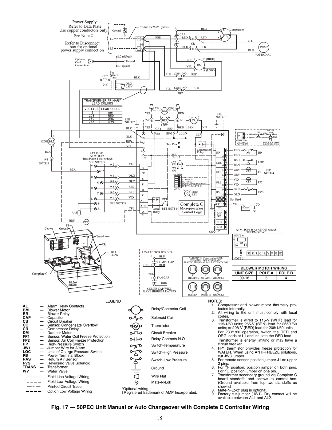
BLOWER MOTOR WIRING
UNIT SIZE | POLE A | POLE B |
| 5 | 4 |
NOTES:
1.Compressor and blower motor thermally pro- tected internally.
2.All wiring to the unit must comply with local codes.
3.Transformer is wired to
For 230/1/60 operation, switch the RED and ORG leads at L1 and insulate the RED lead. Transformer is energy limiting or may have a circuit breaker.
4.FP1 thermistor provides freeze protection for WATER. When using
5.For remote sensor, position jumper J1 on upper 2 pins.
6.For °F position, position jumper on both pins. For °C, position jumper on one pin.
7.Transformer secondary ground via Complete C board standoffs and screws to control box. (Ground available from top two standoffs as shown.)
8.
9.
Fig. 17 — 50PEC Unit Manual or Auto Changeover with Complete C Controller Wiring
18