50RLP specifications
The Carrier 50RLP is a well-regarded air conditioning unit that combines efficiency, durability, and innovative technology to provide optimal cooling solutions for both residential and commercial applications. This model is part of Carrier's extensive lineup designed to meet various climate control needs.One of the standout features of the Carrier 50RLP is its high energy efficiency rating. Equipped with a scroll compressor, the system operates efficiently, reducing energy consumption significantly. This not only lowers utility bills for the user but also contributes to a smaller carbon footprint, making it an environmentally friendly choice. The unit adheres to stringent energy standards, often exceeding the minimum requirements, which is especially advantageous in regions with strict energy codes.
The Carrier 50RLP also boasts advanced refrigerant technology. Utilizing R-410A refrigerant, the unit is designed to minimize ozone depletion potential. R-410A is known for its effectiveness in heat exchange as well as its stability, thus ensuring reliable performance over the unit's lifespan. Additionally, the option for variable refrigerant flow technology in some variants of the 50RLP allows for precise temperature control, making it adaptable to varying cooling needs.
Durability is another hallmark of the Carrier 50RLP. The unit features a robust construction with weatherproof materials that withstand harsh environmental conditions. This resilience is crucial for outdoor installations and contributes to a longer lifespan. Carrier also incorporates innovative sound reduction technologies, allowing the unit to operate quietly, making it suitable for both residential and commercial settings where noise levels are a concern.
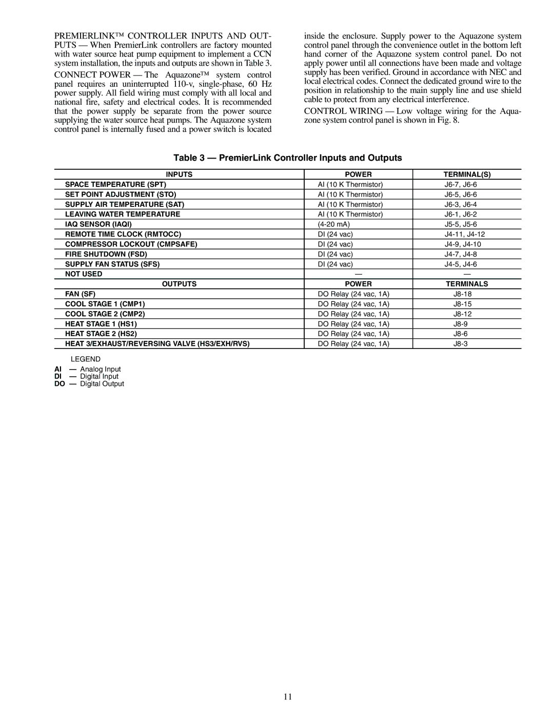
Furthermore, the Carrier 50RLP is equipped with advanced controls. The inclusion of smart thermostat capabilities enables users to manage and schedule cooling efficiently, optimizing energy usage based on occupancy or time of day. These controls can often be integrated with home automation systems, enhancing user convenience.
In summary, the Carrier 50RLP air conditioning unit brings together high efficiency, innovative refrigerant technology, robust durability, and advanced smart controls. Its design not only meets the cooling demands of various spaces but also promotes energy savings and environmental sustainability. Ideal for both residential and commercial applications, the Carrier 50RLP stands out as a reliable choice for maintaining comfortable indoor environments. Whether for new installations or replacements, this model is a testament to Carrier's commitment to quality and innovation in HVAC technology.
