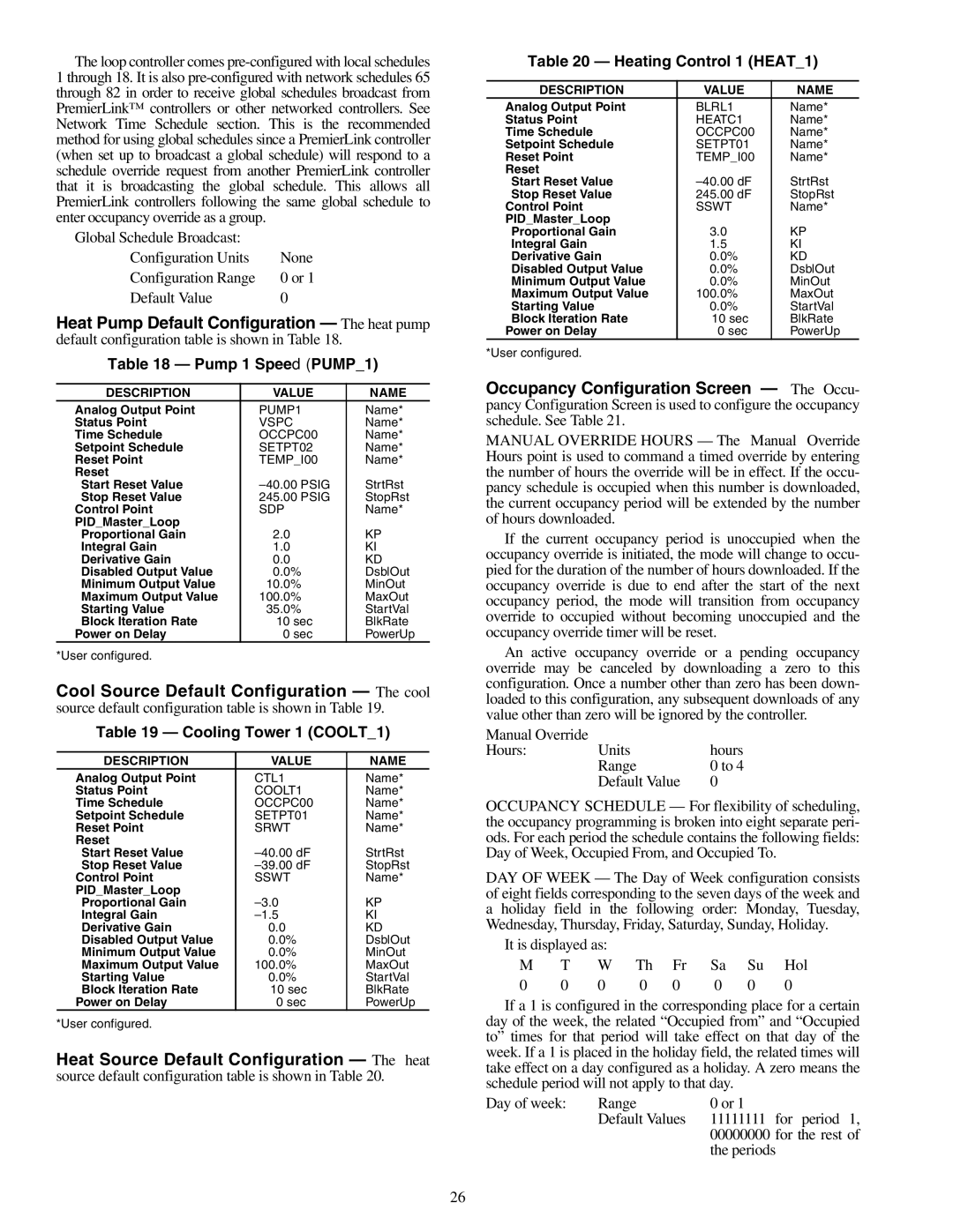
Carrier 50RLP Pump 1 Speed PUMP, Cooling Tower 1 COOLT, Heating Control 1 HEAT

Models: 50RLP

1 28
Download 28 pages 1.7 Kb
Page 26
Image 26

The loop controller comes pre-configured with local schedules 1 through 18. It is also pre-configured with network schedules 65 through 82 in order to receive global schedules broadcast from PremierLink™ controllers or other networked controllers. See Network Time Schedule section. This is the recommended method for using global schedules since a PremierLink controller (when set up to broadcast a global schedule) will respond to a schedule override request from another PremierLink controller that it is broadcasting the global schedule. This allows all PremierLink controllers following the same global schedule to enter occupancy override as a group.

Global Schedule Broadcast:


Configuration Units

None

Configuration Range

0 or 1

Default Value

0

Heat Pump Default Configuration — The heat pump default configuration table is shown in Table 18.

Table 18 — Pump 1 Speed (PUMP_1)

DESCRIPTION

VALUE

NAME

Analog Output Point

PUMP1

Name*

Status Point

VSPC

Name*

Time Schedule

OCCPC00

Name*

Setpoint Schedule

SETPT02

Name*

Reset Point

TEMP_I00

Name*

Reset


Start Reset Value

–40.00 PSIG

StrtRst

Stop Reset Value

245.00 PSIG

StopRst

Control Point

SDP

Name*

PID_Master_Loop


Proportional Gain

2.0

KP

Integral Gain

1.0

KI

Derivative Gain

0.0

KD

Disabled Output Value

0.0%

DsblOut

Minimum Output Value

10.0%

MinOut

Maximum Output Value

100.0%

MaxOut

Starting Value

35.0%

StartVal

Block Iteration Rate

10 sec

BlkRate

Power on Delay

0 sec

PowerUp

*User configured.


Cool Source Default Configuration — The cool source default configuration table is shown in Table 19.

Table 19 — Cooling Tower 1 (COOLT_1)

DESCRIPTION

VALUE

NAME

Analog Output Point

CTL1

Name*

Status Point

COOLT1

Name*

Time Schedule

OCCPC00

Name*

Setpoint Schedule

SETPT01

Name*

Reset Point

SRWT

Name*

Reset


Start Reset Value

–40.00 dF

StrtRst

Stop Reset Value

–39.00 dF

StopRst

Control Point

SSWT

Name*

PID_Master_Loop


Proportional Gain

–3.0

KP

Integral Gain

–1.5

KI

Derivative Gain

0.0

KD

Disabled Output Value

0.0%

DsblOut

Minimum Output Value

0.0%

MinOut

Maximum Output Value

100.0%

MaxOut

Starting Value

0.0%

StartVal

Block Iteration Rate

10 sec

BlkRate

Power on Delay

0 sec

PowerUp

*User configured.


Heat Source Default Configuration — The heat source default configuration table is shown in Table 20.

Table 20 — Heating Control 1 (HEAT_1)

DESCRIPTION

VALUE

NAME

Analog Output Point

BLRL1

Name*

Status Point

HEATC1

Name*

Time Schedule

OCCPC00

Name*

Setpoint Schedule

SETPT01

Name*

Reset Point

TEMP_I00

Name*

Reset


Start Reset Value

–40.00 dF

StrtRst

Stop Reset Value

245.00 dF

StopRst

Control Point

SSWT

Name*

PID_Master_Loop


Proportional Gain

3.0

KP

Integral Gain

1.5

KI

Derivative Gain

0.0%

KD

Disabled Output Value

0.0%

DsblOut

Minimum Output Value

0.0%

MinOut

Maximum Output Value

100.0%

MaxOut

Starting Value

0.0%

StartVal

Block Iteration Rate

10 sec

BlkRate

Power on Delay

0 sec

PowerUp

*User configured.


Occupancy Configuration Screen — The Occu- pancy Configuration Screen is used to configure the occupancy schedule. See Table 21.

MANUAL OVERRIDE HOURS — The Manual Override Hours point is used to command a timed override by entering the number of hours the override will be in effect. If the occu- pancy schedule is occupied when this number is downloaded, the current occupancy period will be extended by the number of hours downloaded.

If the current occupancy period is unoccupied when the occupancy override is initiated, the mode will change to occu- pied for the duration of the number of hours downloaded. If the occupancy override is due to end after the start of the next occupancy period, the mode will transition from occupancy override to occupied without becoming unoccupied and the occupancy override timer will be reset.

An active occupancy override or a pending occupancy override may be canceled by downloading a zero to this configuration. Once a number other than zero has been down- loaded to this configuration, any subsequent downloads of any value other than zero will be ignored by the controller.

Manual Override


Hours:

Units

hours


Range

0 to 4


Default Value

0

OCCUPANCY SCHEDULE — For flexibility of scheduling, the occupancy programming is broken into eight separate peri- ods. For each period the schedule contains the following fields: Day of Week, Occupied From, and Occupied To.

DAY OF WEEK — The Day of Week configuration consists of eight fields corresponding to the seven days of the week and a holiday field in the following order: Monday, Tuesday, Wednesday, Thursday, Friday, Saturday, Sunday, Holiday.

It is displayed as:

M

T

W

Th

Fr

Sa

Su

Hol

0

0

0

0

0

0

0

0

If a 1 is configured in the corresponding place for a certain day of the week, the related “Occupied from” and “Occupied to” times for that period will take effect on that day of the week. If a 1 is placed in the holiday field, the related times will take effect on a day configured as a holiday. A zero means the schedule period will not apply to that day.

Day of week:

Range

0 or 1


Default Values

11111111 for period 1,


00000000 for the rest of


the periods

26

Page 26
Image 26
Carrier 50RLP installation instructions Pump 1 Speed PUMP, Cooling Tower 1 COOLT, Heating Control 1 HEAT