REMOTE OCCUPANCY — This input is used to provide an external clock input to enable all 18 of the local schedules, start the loop pumps, and enable loop temperature control.

Remote Occupancy:


Display Units

Discrete ASCII

Default Value

Disable

Display Range

Enable/Disable

Network Access

Read/Write

SYSTEM/SHUT DOWN — This discrete input is used to provide a signal from the fire alarm panel that will shut down the Aquazone™ System Control Panel, disable the system zone relays, and send out a command to shut down the water source heat pumps.

System/Shut Down:


Display Units

Discrete ASCII

Default Value

Enable

Display Range

EmStop/Enable

Network Access

Read/Write

OVERRIDE INPUT FOR ZONE 1-18 — These inputs are used to sense an external dry contact that override/enable each of the 18 local schedules, start the loop pumps, and enable loop temperature control.

Override Input for Zone 1-18


Display Units

Discrete ASCII

Default Value

Disable

Display Range

Enable/Disable

Network Access

Read/Write

PUMP NUMBER 1 — When the Aquazone System Control Panel is configured for variable speed pumping, this point displays the speed of Pump 1, as determined by a PID loop set to control supply water pressure. When the Aquazone system control panel is configured for constant flow this point will display 0% when the pump is OFF and 100% when the pump is on.

Pump Number 1


Display Units

%

Default Value

0

Display range

0-100

Network Access

Read/Write

PUMP NUMBER 2 — When the Aquazone system control panel is configured for variable speed pumping, this point displays the speed of Pump 2, as determined by a PID loop set to control supply water pressure. When the Aquazone system control panel is configured for constant flow this point will display 0% when the pump is OFF and 100% when the pump is on.

Pump Number 2


Display Units

%

Default Value

0

Display range

0-100

Network Access

Read/Write

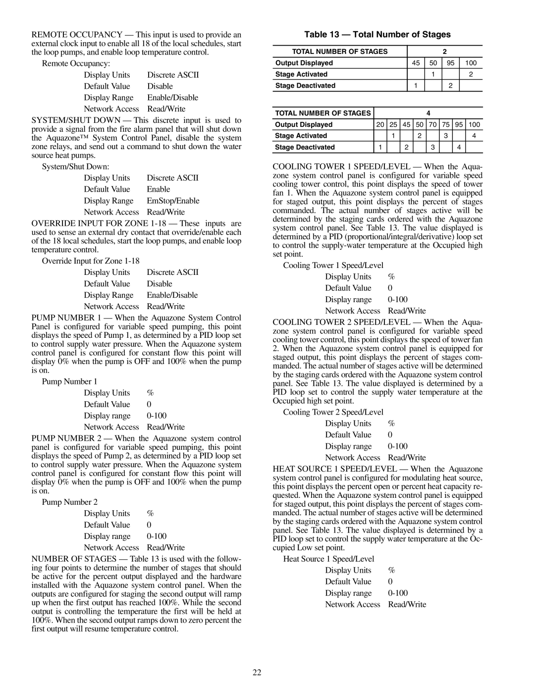
NUMBER OF STAGES — Table 13 is used with the follow- ing four points to determine the number of stages that should be active for the percent output displayed and the hardware installed with the Aquazone system control panel. When the outputs are configured for staging the second output will ramp up when the first output has reached 100%. While the second output is controlling the temperature the first will be held at 100%. When the second output ramps down to zero percent the first output will resume temperature control.

Table 13 — Total Number of Stages

TOTAL NUMBER OF STAGES


2


Output Displayed

45

50

95

100


Stage Activated

1

2


Stage Deactivated

1

2


TOTAL NUMBER OF STAGES

4


Output Displayed

20

25

45

50

70

75

95

100


Stage Activated

1

2

3

4


Stage Deactivated

1

2

3

4


COOLING TOWER 1 SPEED/LEVEL — When the Aqua- zone system control panel is configured for variable speed cooling tower control, this point displays the speed of tower fan 1. When the Aquazone system control panel is equipped for staged output, this point displays the percent of stages commanded. The actual number of stages active will be determined by the staging cards ordered with the Aquazone system control panel. See Table 13. The value displayed is determined by a PID (proportional/integral/derivative) loop set to control the supply-water temperature at the Occupied high set point.

Cooling Tower 1 Speed/Level

Display Units

%

Default Value

0

Display range

0-100

Network Access

Read/Write

COOLING TOWER 2 SPEED/LEVEL — When the Aqua- zone system control panel is configured for variable speed cooling tower control, this point displays the speed of tower fan

2.When the Aquazone system control panel is equipped for staged output, this point displays the percent of stages com- manded. The actual number of stages active will be determined by the staging cards ordered with the Aquazone system control panel. See Table 13. The value displayed is determined by a PID loop set to control the supply water temperature at the Occupied high set point.

Cooling Tower 2 Speed/Level

Display Units

%

Default Value

0

Display range

0-100

Network Access

Read/Write

HEAT SOURCE 1 SPEED/LEVEL — When the Aquazone system control panel is configured for modulating heat source, this point displays the percent open or percent heat capacity re- quested. When the Aquazone system control panel is equipped for staged output, this point displays the percent of stages com- manded. The actual number of stages active will be determined by the staging cards ordered with the Aquazone system control panel. See Table 13. The value displayed is determined by a PID loop set to control the supply water temperature at the Oc- cupied Low set point.

Heat Source 1 Speed/Level


Display Units

%

Default Value

0

Display range

0-100

Network Access

Read/Write

22

Page 22
Image 22
Carrier 50RLP installation instructions Total Number of Stages, Output Displayed, Stage Activated Stage Deactivated

50RLP specifications

The Carrier 50RLP is a well-regarded air conditioning unit that combines efficiency, durability, and innovative technology to provide optimal cooling solutions for both residential and commercial applications. This model is part of Carrier's extensive lineup designed to meet various climate control needs.

One of the standout features of the Carrier 50RLP is its high energy efficiency rating. Equipped with a scroll compressor, the system operates efficiently, reducing energy consumption significantly. This not only lowers utility bills for the user but also contributes to a smaller carbon footprint, making it an environmentally friendly choice. The unit adheres to stringent energy standards, often exceeding the minimum requirements, which is especially advantageous in regions with strict energy codes.

The Carrier 50RLP also boasts advanced refrigerant technology. Utilizing R-410A refrigerant, the unit is designed to minimize ozone depletion potential. R-410A is known for its effectiveness in heat exchange as well as its stability, thus ensuring reliable performance over the unit's lifespan. Additionally, the option for variable refrigerant flow technology in some variants of the 50RLP allows for precise temperature control, making it adaptable to varying cooling needs.

Durability is another hallmark of the Carrier 50RLP. The unit features a robust construction with weatherproof materials that withstand harsh environmental conditions. This resilience is crucial for outdoor installations and contributes to a longer lifespan. Carrier also incorporates innovative sound reduction technologies, allowing the unit to operate quietly, making it suitable for both residential and commercial settings where noise levels are a concern.

Furthermore, the Carrier 50RLP is equipped with advanced controls. The inclusion of smart thermostat capabilities enables users to manage and schedule cooling efficiently, optimizing energy usage based on occupancy or time of day. These controls can often be integrated with home automation systems, enhancing user convenience.

In summary, the Carrier 50RLP air conditioning unit brings together high efficiency, innovative refrigerant technology, robust durability, and advanced smart controls. Its design not only meets the cooling demands of various spaces but also promotes energy savings and environmental sustainability. Ideal for both residential and commercial applications, the Carrier 50RLP stands out as a reliable choice for maintaining comfortable indoor environments. Whether for new installations or replacements, this model is a testament to Carrier's commitment to quality and innovation in HVAC technology.