SECTION 2
TROUBLESHOOTING
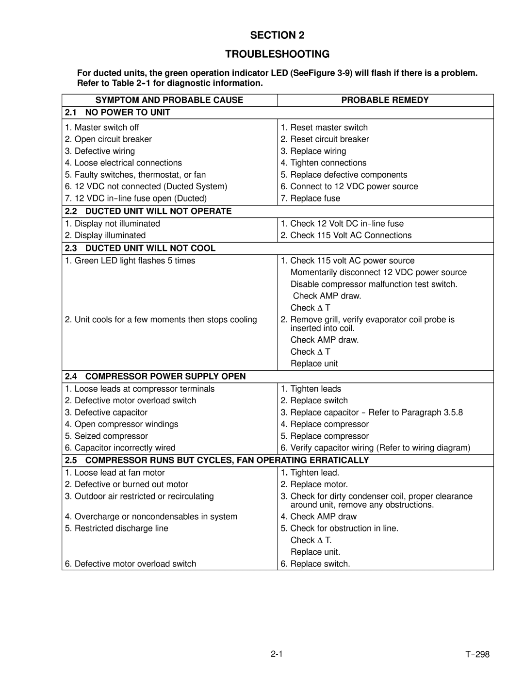
For ducted units, the green operation indicator LED (SeeFigure
| SYMPTOM AND PROBABLE CAUSE |
| PROBABLE REMEDY |
2.1 NO POWER TO UNIT |
|
| |
|
|
|
|
1. | Master switch off | 1. | Reset master switch |
2. | Open circuit breaker | 2. | Reset circuit breaker |
3. | Defective wiring | 3. | Replace wiring |
4. | Loose electrical connections | 4. | Tighten connections |
5. | Faulty switches, thermostat, or fan | 5. | Replace defective components |
6. | 12 VDC not connected (Ducted System) | 6. | Connect to 12 VDC power source |
7. | 12 VDC | 7. | Replace fuse |
|
|
| |
2.2 DUCTED UNIT WILL NOT OPERATE |
|
| |
|
|
|
|
1. | Display not illuminated | 1. | Check 12 Volt DC |
2. | Display illuminated | 2. | Check 115 Volt AC Connections |
|
|
| |
2.3 DUCTED UNIT WILL NOT COOL |
|
| |
|
|
|
|
1. | Green LED light flashes 5 times | 1. | Check 115 volt AC power source |
|
|
| Momentarily disconnect 12 VDC power source |
|
|
| Disable compressor malfunction test switch. |
|
|
| Check AMP draw. |
|
|
| Check ∆ T |
2. | Unit cools for a few moments then stops cooling | 2. | Remove grill, verify evaporator coil probe is |
|
|
| inserted into coil. |
|
|
| Check AMP draw. |
|
|
| Check ∆ T |
|
|
| Replace unit |
|
|
| |
2.4 COMPRESSOR POWER SUPPLY OPEN |
|
| |
|
|
|
|
1. | Loose leads at compressor terminals | 1. | Tighten leads |
2. | Defective motor overload switch | 2. | Replace switch |
3. | Defective capacitor | 3. | Replace capacitor |
4. | Open compressor windings | 4. | Replace compressor |
5. | Seized compressor | 5. | Replace compressor |
6. | Capacitor incorrectly wired | 6. | Verify capacitor wiring (Refer to wiring diagram) |
|
| ||
2.5 COMPRESSOR RUNS BUT CYCLES, FAN OPERATING ERRATICALLY | |||
|
|
| |
1. | Loose lead at fan motor | 1. Tighten lead. | |
2. | Defective or burned out motor | 2. | Replace motor. |
3. | Outdoor air restricted or recirculating | 3. | Check for dirty condenser coil, proper clearance |
|
|
| around unit, remove any obstructions. |
4. | Overcharge or noncondensables in system | 4. | Check AMP draw |
5. | Restricted discharge line | 5. | Check for obstruction in line. |
|
|
| Check ∆ T. |
|
|
| Replace unit. |
6. | Defective motor overload switch | 6. | Replace switch. |