SECTION 3
SERVICE AND MAINTENANCE
3.1 PREVENTATIVE MAINTENANCE
Thoroughly clean base pan, motors, fan wheels, and other components.
Clean cover and ceiling grill. Mild detergents reduce electrostatic charges on plastic sections of the grill and are good cleaners.
![]() CAUTION
CAUTION
Do not use carbon tetrachloride, solvents, or waxes containing solvents to clean plas- tic sections.
NOTE
Check to ensure that piping is not vibrating against side of the unit.
NOTE
For proper cleaning and flushing, use a UL approved refrigerant recovery/recycling system.
NOTE
Refrigerant removal must always include recovering the refrigerant, not allowing it to escape to the atmosphere.
![]() WARNING
WARNING
Before working on the unit be sure to first disconnect all electric power to the unit to avoid the possibility of electrical shock and personal injury. Before disconnecting, dis- charge capacitors by shorting across the capacitors terminals (Refer to paragraph 3.5.8)
![]() WARNING
WARNING
Shield coils with cardboard to protect hands against injury from sharp metal edges when removing compressor and oth- er components.
3.3 CEILING UNIT
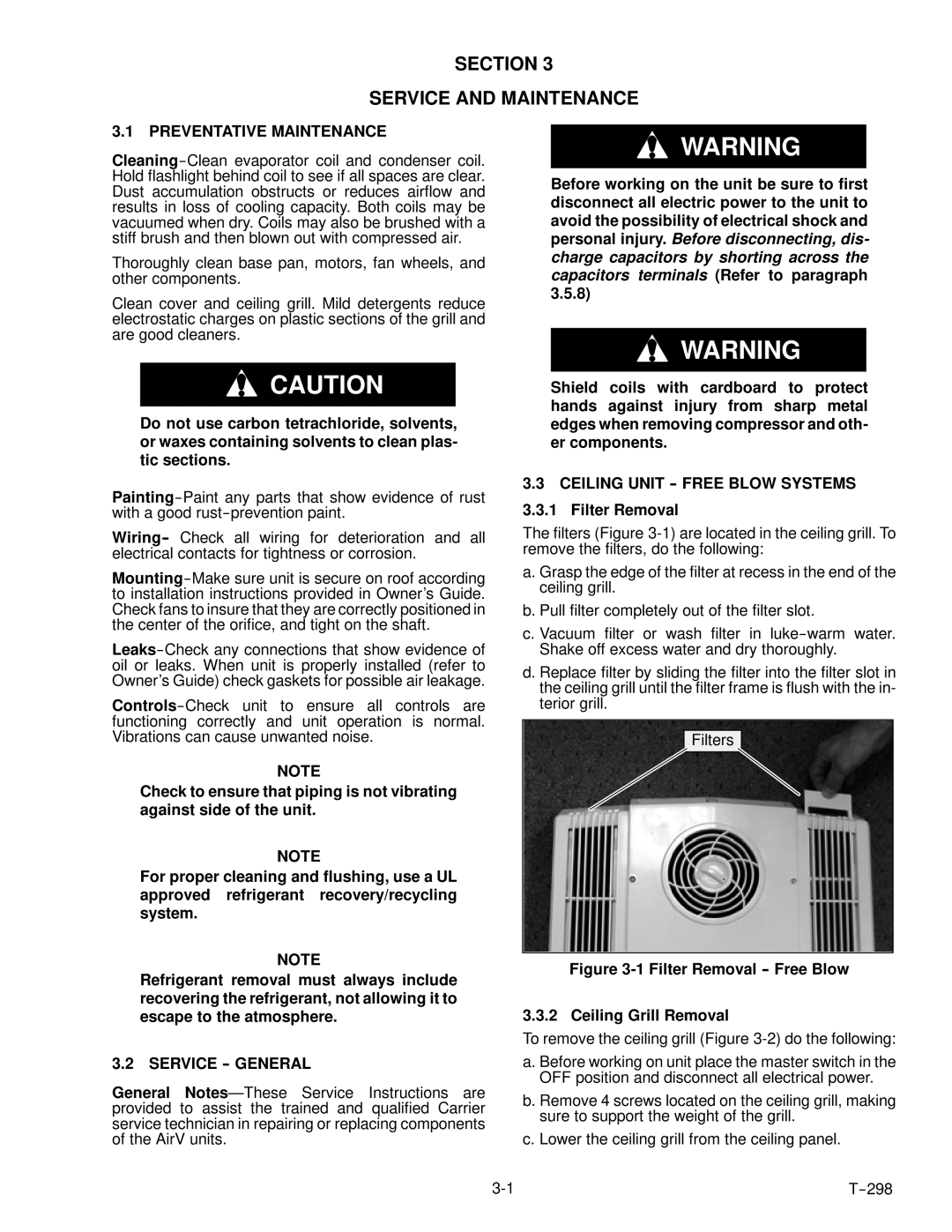
The filters (Figure
a. Grasp the edge of the filter at recess in the end of the ceiling grill.
b. Pull filter completely out of the filter slot.
c. Vacuum filter or wash filter in
d. Replace filter by sliding the filter into the filter slot in the ceiling grill until the filter frame is flush with the in- terior grill.
Filters
Figure 3-1 Filter Removal -- Free Blow
3.3.2 Ceiling Grill Removal
To remove the ceiling grill (Figure
3.2 SERVICE -- GENERAL
General
a. Before working on unit place the master switch in the OFF position and disconnect all electrical power.
b. Remove 4 screws located on the ceiling grill, making sure to support the weight of the grill.
c. Lower the ceiling grill from the ceiling panel.