3.11.2 Timeguard Timer
A
3.11.3 Cycle Timer
In normal cooling (and heating) operation the thermostat will not allow more than 4 equipment cycles per hour (or 1 cycle every 15 minutes). Both the “Y” (cooling) and “W” (heating) outputs have a
minutes regardless of demand). However, pressing UP and FAN buttons simultaneously or changing the set point will override the timer for 1 cycle.
3.11.4 Minimum On Timer
Once the equipment has turned on, it will remain on for a minimum of 2 minutes regardless of demand. However, the equipment can turn off in less than 2 minutes if a change in set point, or a changein mode occurs.
3.11.5 Error Messages
E4 will be displayed if the thermostat has an internal memory failure. If E4 appears, replace the thermostat.
----(two dashes) will be displayed if the thermostat cannot properly read the room temperature. If
appears, replace the thermostat.
UPPER UNIT
![]() Factory Wiring
Factory Wiring![]()
![]() Field Wiring
Field Wiring![]()
|
|
|
|
|
|
|
|
|
|
|
|
|
|
|
|
|
|
|
|
|
|
|
|
|
|
| Motor |
|
|
|
| Comp. | |||||||||
|
|
|
|
|
|
|
|
|
|
|
|
|
|
|
|
|
|
|
|
|
|
|
|
| 1 | 2 | 3 | 4 |
|
|
|
| 2 | 1 |
| ||||||
|
|
|
|
|
|
|
|
|
|
|
|
|
|
|
|
|
|
|
|
|
|
|
|
|
|
|
|
|
|
|
|
|
|
|
|
|
|
|
|
|
|
|
|
|
|
|
|
|
|
|
|
|
|
|
|
|
|
|
|
|
|
|
|
|
|
|
|
|
|
|
|
|
|
|
|
|
|
|
|
|
|
|
|
|
|
|
|
|
|
|
|
|
|
|
|
|
|
|
|
|
|
|
|
|
|
|
|
|
|
|
|
|
|
|
|
|
|
|
|
|
|
|
|
|
|
|
|
|
|
|
|
|
|
|
|
|
|
|
|
|
|
|
|
|
|
|
|
|
|
|
|
|
|
|
|
|
|
|
|
|
|
|
|
|
|
|
|
1 | 2 | 3 | 4 |
|
|
| J |
|
|
|
|
| ||
|
|
|
|
|
|
|
|
|
|
|
|
|
|
|
|
|
|
|
|
|
|
|
|
|
| L |
|
|
|
|
|
|
|
|
|
|
|
|
|
|
|
|
|
|
|
|
|
|
|
|
|
|
|
|
|
|
|
|
|
|
|
|
|
|
|
|
|
|
|
| N2 |
|
|
|
|
|
|
|
|
|
|
|
|
|
|
|
|
| |
|
|
|
|
|
|
|
|
|
|
|
|
|
|
|
|
|
|
|
|
|
|
|
|
|
|
|
|
|
|
|
|
|
|
|
|
|
|
|
|
| N1 |
|
|
|
POWERBOX |
|
|
|
|
|
|
| |||||||
|
|
|
|
|
|
|
| |||||||
|
|
|
|
|
|
|
| |||||||
ASSEMBLY |
|
|
|
|
|
|
|
| ||||||
|
|
|
| 1 |
|
| W | |||||||
|
|
|
|
|
|
|
|
|
|
|
|
| ||
|
|
|
|
|
|
|
|
|
|
|
|
|
|
|
115V AC High Voltage
Power Supply
THERMOSTAT
2 |
|
|
| Y |
|
|
| ||
3 |
|
|
| GH |
|
|
| ||
4 |
|
|
| GL |
|
|
| ||
|
|
|
|
|
5 |
|
|
| C |
|
|
| ||
|
|
|
|
|
Y
GH
GL
R
C
COOL (Compressor)
FAN (High)
FAN (Low)
12VDC LowVoltage
Power Supply
CEILING UNIT
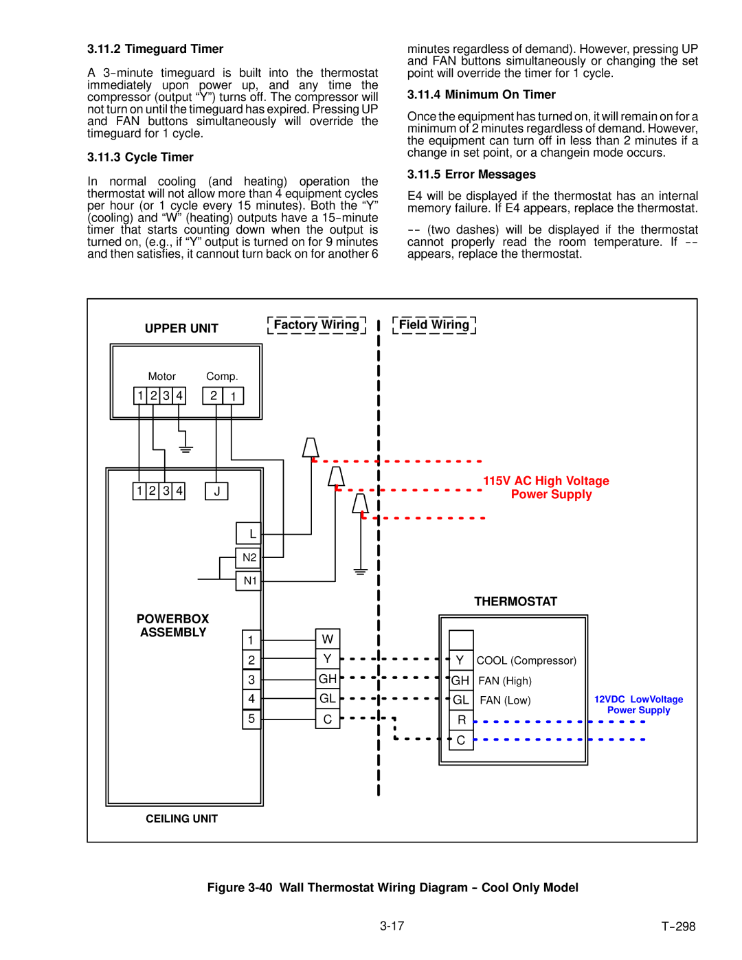
Figure |
|
|
