3.5.2 Compressor Replacement
Observe the same procedures for rotary compressors as for reciprocating compressors.
a. Follow all safety codes. Reminder: use protective goggles, work gloves, and water soaked quenching cloth.
b. Remove exterior cover. refer to paragraph 3.5.1. Dis- connect all wiring from the compressor.
c.Apply
d.Recover the refrigerant charge from the unit. After re- covering, cut the discharge and suction line process tubes below the tube crimps. If you choose a good tubing location for cutting the refrigeration lines ini- tially, the location is easily accessible when making the final joints.
![]() WARNING
WARNING
Oil vapor in piping stubs can ignite from torch flame and cause serious injury. Exer- cise extreme care when brazing, and keep brazing cloth and fire extinguisher handy for emergency use.
e.Connect a nitrogen supply to the unit at one of the line
f.Remove compressor from unit (3 bolts).
g.Remove
h.Clean system: add or replace liquid line filter drier. For proper cleaning and flushing use a UL approved re- frigerant recycling system.
i.Install new compressor and braze into place with
j.Connect wiring: replace wire terminals if necessary.
k.Proceed with evacuation and charging (15.9 OZ.
.45 KG R22). Pinch off lines where angle valves were added. Cut off angle valves above
l.Start up unit.
3.5.3 Control Box Assembly Removal
To remove the control box assembly, do the following:
a.Remove exterior cover assembly. Refer to paragraph 3.5.1.
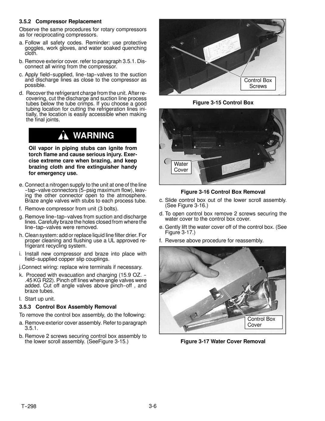
b.Remove 2 screws securing control box assembly to the lower scroll assembly. (SeeFigure
Control Box |
Screws |
Figure 3-15 Control Box
Water
Cover
Figure 3-16 Control Box Removal
c. Slide control box out of the lower scroll assembly. (See Figure
d. To open control box remove 2 screws securing the water cover to the control box cover.
e. Gently lift the water cover off of the control box. (See Figure
f. Reverse above procedure for reassembly.
Control Box
Cover
