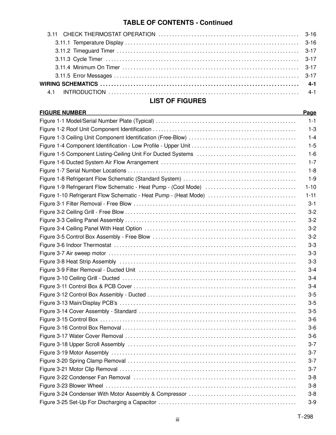
TABLE OF CONTENTS - Continued
3.11 CHECK THERMOSTAT OPERATION . . . . . . . . . . . . . . . . . . . . . . . . . . . . . . . . . . . . . . . . . . . . . . . . . . . 3-16
3.11.1 Temperature Display . . . . . . . . . . . . . . . . . . . . . . . . . . . . . . . . . . . . . . . . . . . . . . . . . . . . . . . . . . . . . . .
3.11.2 Timeguard Timer . . . . . . . . . . . . . . . . . . . . . . . . . . . . . . . . . . . . . . . . . . . . . . . . . . . . . . . . . . . . . . . . . .
3.11.3 Cycle Timer . . . . . . . . . . . . . . . . . . . . . . . . . . . . . . . . . . . . . . . . . . . . . . . . . . . . . . . . . . . . . . . . . . . . . .
3.11.4 Minimum On Timer . . . . . . . . . . . . . . . . . . . . . . . . . . . . . . . . . . . . . . . . . . . . . . . . . . . . . . . . . . . . . . . .
3.11.5 Error Messages . . . . . . . . . . . . . . . . . . . . . . . . . . . . . . . . . . . . . . . . . . . . . . . . . . . . . . . . . . . . . . . . . . .
WIRING SCHEMATICS . . . . . . . . . . . . . . . . . . . . . . . . . . . . . . . . . . . . . . . . . . . . . . . . . . . . . . . . . . . . . . . . . . . . . . . .
4.1 INTRODUCTION . . . . . . . . . . . . . . . . . . . . . . . . . . . . . . . . . . . . . . . . . . . . . . . . . . . . . . . . . . . . . . . . . . . . .
LIST OF FIGURES
FIGURE NUMBER | Page |
Figure | |
Figure | |
Figure | |
Figure | |
Figure | |
Figure | |
Figure | |
Figure | |
Figure | |
Figure | |
Figure | |
Figure | |
Figure | |
Figure | |
Figure | |
Figure | |
Figure | |
Figure | |
Figure | |
Figure | |
Figure | |
Figure | |
Figure | |
Figure | |
Figure | |
Figure | |
Figure | |
Figure | |
Figure | |
Figure | |
Figure | |
Figure | |
Figure | |
Figure | |
Figure | |
iii | |
|
