Heating
1.Purge gas supply line of air by opening union ahead of gas valve. If gas odor is detected, tighten union and wait 5 minutes before proceeding.
2.Turn on electrical supply and open manual gas valve.
3.Set system switch selector at HEAT position and fan switch at AUTO. or ON position. Set heating temperature lever above room temperature.
4.The
5.After a call for heating, the main burners should light within 5 seconds. If the burner does not light, then there is a
ADJUST GAS INPUT — The gas input to the unit is deter- mined by measuring the gas flow at the meter or by measuring the manifold pressure. Measuring the gas flow at the meter is recommended for natural gas units. The manifold pressure must be measured to determine the input of propane gas units.
Measure Gas Flow (Natural Gas Units) — Minor adjustment to the gas flow can be made by changing the manifold pressure. The manifold pressure must be maintained between 3.4 and
3.6in. wg. If larger adjustments are required, change main burner orifices following the recommendations of national and local codes. Unit must be operating with both W1 and W2 en- ergized
NOTE: All other appliances that use the same meter must be turned off when gas flow is measured at the meter.
Proceed as follows:
1.Turn off gas supply to unit. Turn off electric supply to unit and install lockout tag.
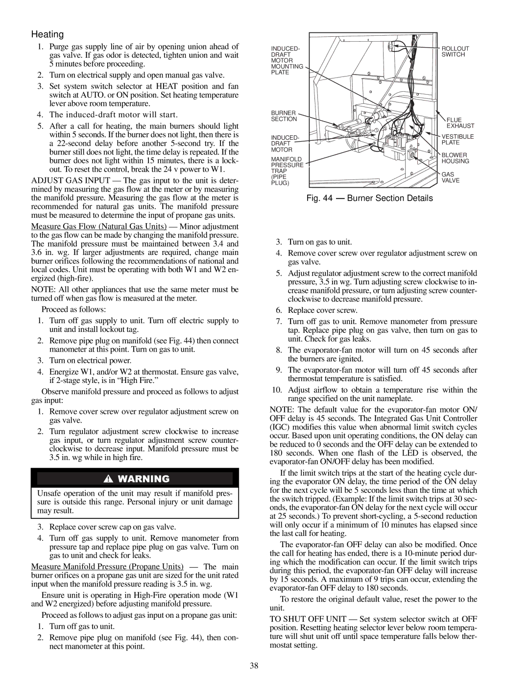
2.Remove pipe plug on manifold (see Fig. 44) then connect manometer at this point. Turn on gas to unit.
3.Turn on electrical power.
4.Energize W1, and/or W2 at thermostat. Ensure gas valve, if
Observe manifold pressure and proceed as follows to adjust gas input:
1.Remove cover screw over regulator adjustment screw on gas valve.
2.Turn regulator adjustment screw clockwise to increase gas input, or turn regulator adjustment screw counter- clockwise to decrease input. Manifold pressure must be 3.5 in. wg while in high fire.
Unsafe operation of the unit may result if manifold pres- sure is outside this range. Personal injury or unit damage may result.
3.Replace cover screw cap on gas valve.
4.Turn off gas supply to unit. Remove manometer from pressure tap and replace pipe plug on gas valve. Turn on gas to unit and check for leaks.
Measure Manifold Pressure (Propane Units) — The main burner orifices on a propane gas unit are sized for the unit rated input when the manifold pressure reading is 3.5 in. wg.
Ensure unit is operating in
Proceed as follows to adjust gas input on a propane gas unit:
1.Turn off gas to unit.
2.Remove pipe plug on manifold (see Fig. 44), then con- nect manometer at this point.
INDUCED- | ROLLOUT |
DRAFT | SWITCH |
MOTOR |
|
MOUNTING |
|
PLATE |
|
BURNER |
| |
SECTION | FLUE | |
| EXHAUST | |
INDUCED- | VESTIBULE | |
DRAFT | PLATE | |
MOTOR | BLOWER | |
MANIFOLD | ||
HOUSING | ||
PRESSURE | ||
| ||
TRAP | GAS | |
(PIPE | ||
VALVE | ||
PLUG) | ||
|
Fig. 44 — Burner Section Details
3.Turn on gas to unit.
4.Remove cover screw over regulator adjustment screw on gas valve.
5.Adjust regulator adjustment screw to the correct manifold pressure, 3.5 in wg. Turn adjusting screw clockwise to in- crease manifold pressure, or turn adjusting screw counter- clockwise to decrease manifold pressure.
6.Replace cover screw.
7.Turn off gas to unit. Remove manometer from pressure tap. Replace pipe plug on gas valve, then turn on gas to unit. Check for gas leaks.
8.The
9.The
10.Adjust airflow to obtain a temperature rise within the range specified on the unit nameplate.
NOTE: The default value for the
If the limit switch trips at the start of the heating cycle dur- ing the evaporator ON delay, the time period of the ON delay for the next cycle will be 5 seconds less than the time at which the switch tripped. (Example: If the limit switch trips at 30 sec- onds, the
The
To restore the original default value, reset the power to the unit.
TO SHUT OFF UNIT — Set system selector switch at OFF position. Resetting heating selector lever below room tempera- ture will shut unit off until space temperature falls below ther- mostat setting.
38