To access burner section, slide the sliding burner partition out of the unit.
To inspect blower wheel, shine a flashlight into draft hood opening. If cleaning is required, remove motor and wheel as follows:
1.Slide burner access panel out.
2.Remove the 7 screws that attach
3.The blower wheel can be cleaned at this point. If addi- tional cleaning is required, continue with Steps 4 and 5.
4. To remove blower from the motor shaft, remove
2 setscrews.
5.To remove motor, remove the 4 screws that hold the motor to mounting plate. Remove the motor cooling fan by removing one setscrew. Then remove nuts that hold motor to mounting plate.
6.To reinstall, reverse the procedure outlined above.
Limit Switch — Remove blower access panel (Fig. 6). Limit switch is located on the fan deck.
Burner Ignition — Unit is equipped with a direct spark ignition 100% lockout system. Integrated Gas Unit Controller (IGC) is located in the control box (Fig. 10). The IGC contains a
If lockout occurs, unit may be reset by interrupting power supply to unit for at least 5 seconds.
Table 31 — LED Error Code Description*
LED INDICATION | ERROR CODE DESCRIPTION |
ON | Normal Operation |
OFF | Hardware Failure |
1 Flash† | Evaporator Fan On/Off Delay Modified |
2 Flashes | Limit Switch Fault |
3 Flashes | Flame Sense Fault |
4 Flashes | 4 Consecutive Limit Switch Faults |
5 Flashes | Ignition Lockout Fault |
6 Flashes | |
7 Flashes | Rollout Switch Fault |
8 Flashes | Internal Control Fault |
LEGEND |
|
LED —
*A
†Indicates a code that is not an error. The unit will continue to oper- ate when this code is displayed.
IMPORTANT: Refer to Troubleshooting Tables
Main Burners — To access burners, remove burner ac- cess panel and slide out burner partition. See Fig. 9. At the beginning of each heating season, inspect for deterioration or blockage due to corrosion or other causes. Observe the main burner flames and adjust, if necessary.
When working on gas train, do not hit or plug orifice spuds.
REMOVAL AND REPLACEMENT OF GAS TRAIN (Fig.
1.Shut off manual gas valve.
2.Shut off power to unit.
3.Slide out burner partition. See Fig. 9.
4.Disconnect gas piping at unit gas valve.
5.Remove wires connected to gas valve. Mark each wire.
6.Remove ignitor wires and sensor wires at the Integrated Gas Unit Controller (IGC) (see Fig. 10).
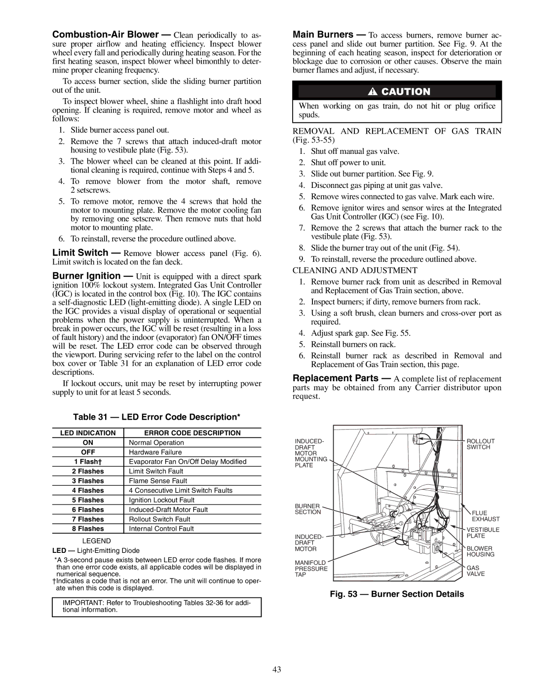
7.Remove the 2 screws that attach the burner rack to the vestibule plate (Fig. 53).
8.Slide the burner tray out of the unit (Fig. 54).
9.To reinstall, reverse the procedure outlined above.
CLEANING AND ADJUSTMENT
1.Remove burner rack from unit as described in Removal and Replacement of Gas Train section, above.
2.Inspect burners; if dirty, remove burners from rack.
3.Using a soft brush, clean burners and
4.Adjust spark gap. See Fig. 55.
5.Reinstall burners on rack.
6.Reinstall burner rack as described in Removal and Replacement of Gas Train section, this page.
Replacement Parts — A complete list of replacement parts may be obtained from any Carrier distributor upon request.
INDUCED- | ROLLOUT |
DRAFT | SWITCH |
MOTOR |
|
MOUNTING |
|
PLATE |
|
BURNER |
|
SECTION | FLUE |
| EXHAUST |
| VESTIBULE |
INDUCED- | PLATE |
DRAFT | BLOWER |
MOTOR | |
| HOUSING |
MANIFOLD | GAS |
PRESSURE | |
TAP | VALVE |
Fig. 53 — Burner Section Details
43