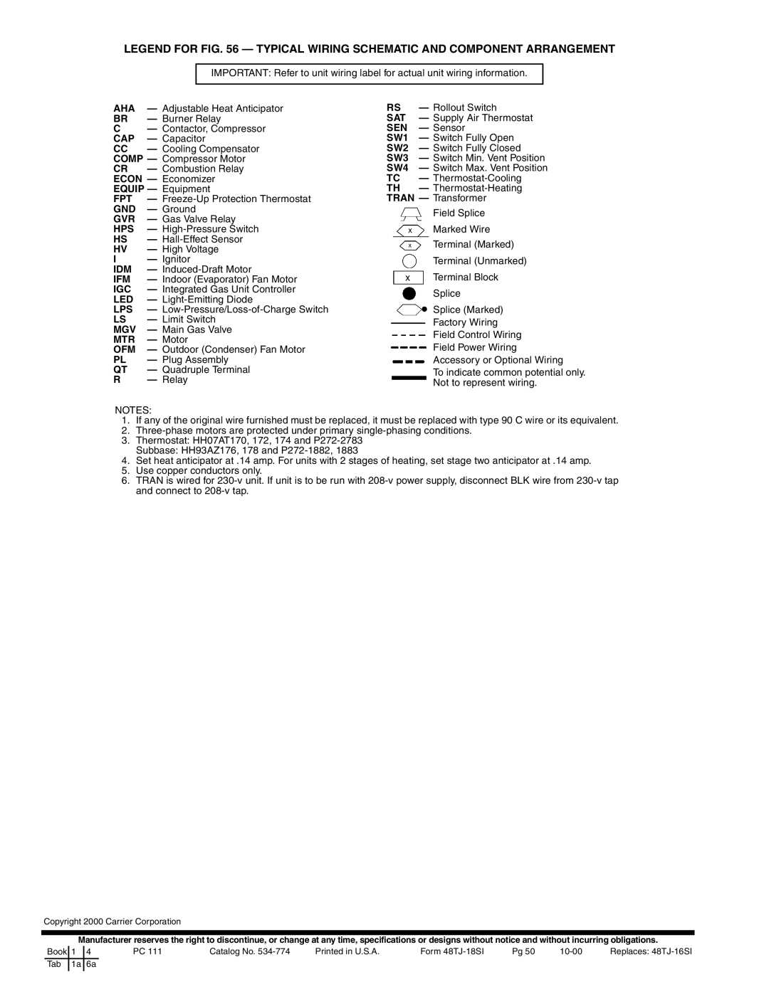
LEGEND FOR FIG. 56 — TYPICAL WIRING SCHEMATIC AND COMPONENT ARRANGEMENT
IMPORTANT: Refer to unit wiring label for actual unit wiring information.
AHA — Adjustable Heat Anticipator BR — Burner Relay
C— Contactor, Compressor CAP — Capacitor
CC — Cooling Compensator COMP — Compressor Motor CR — Combustion Relay ECON — Economizer EQUIP — Equipment
FPT —
GVR — Gas Valve Relay HPS —
I — Ignitor
IDM —
IFM — Indoor (Evaporator) Fan Motor IGC — Integrated Gas Unit Controller LED —
LPS —
MGV — Main Gas Valve MTR — Motor
OFM — Outdoor (Condenser) Fan Motor PL — Plug Assembly
QT — Quadruple Terminal
R — Relay
RS | — Rollout Switch |
SAT | — Supply Air Thermostat |
SEN | — Sensor |
SW1 | — Switch Fully Open |
SW2 | — Switch Fully Closed |
SW3 | — Switch Min. Vent Position |
SW4 | — Switch Max. Vent Position |
TC | — |
TH | — |
TRAN — Transformer
Field Splice
![]() Marked Wire
Marked Wire
Terminal (Marked)
Terminal (Unmarked)
Terminal Block
Splice
Splice (Marked)
Factory Wiring Field Control Wiring Field Power Wiring Accessory or Optional Wiring
To indicate common potential only. Not to represent wiring.
NOTES:
1.If any of the original wire furnished must be replaced, it must be replaced with type 90 C wire or its equivalent.
2.
3.Thermostat: HH07AT170, 172, 174 and
Subbase: HH93AZ176, 178 and
4.Set heat anticipator at .14 amp. For units with 2 stages of heating, set stage two anticipator at .14 amp.
5.Use copper conductors only.
6.TRAN is wired for
Copyright 2000 Carrier Corporation
Manufacturer reserves the right to discontinue, or change at any time, specifications or designs without notice and without incurring obligations.
Book | 1 | 4 | PC 111 | Catalog No. | Printed in U.S.A. | Form | Pg 50 | Replaces: | |
Tab | 1a | 6a |
|
|
|
|
|
|
|
|
|
|
|
|
|
|
|
|
|