MAXIMUM ALLOWABLE
DIFFERENCE (in.)
0.5 | 1.0 | 1.0 |
Fig. 3 — Unit Leveling Tolerances
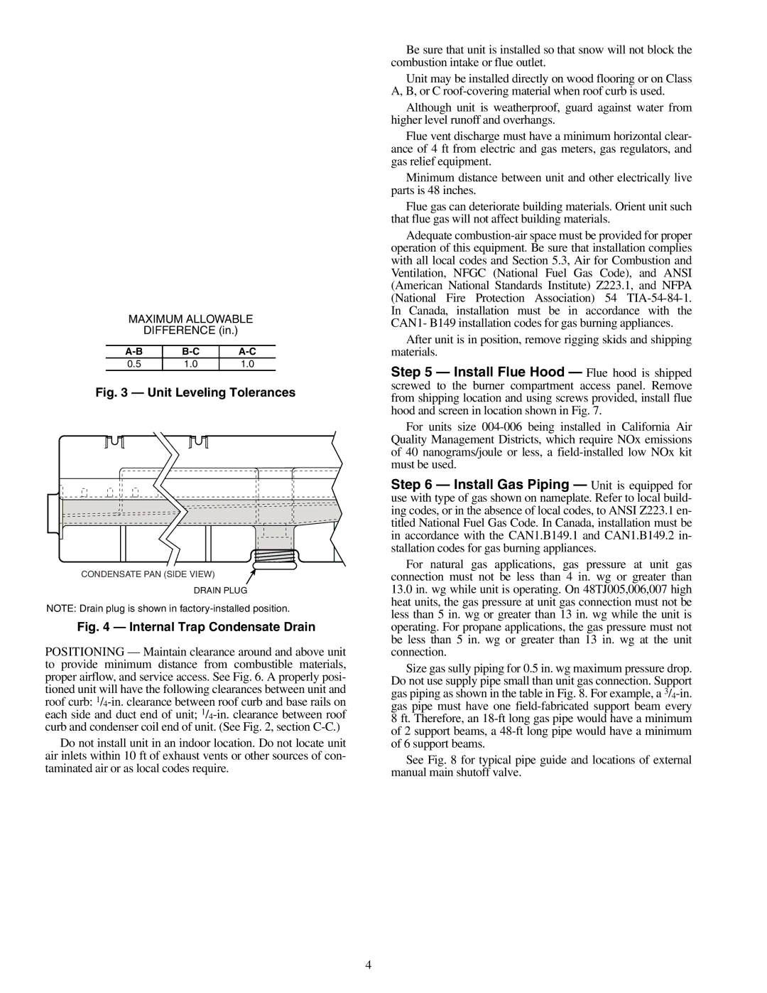
CONDENSATE PAN (SIDE VIEW)
DRAIN PLUG
NOTE: Drain plug is shown in
Fig. 4 — Internal Trap Condensate Drain
POSITIONING — Maintain clearance around and above unit to provide minimum distance from combustible materials, proper airflow, and service access. See Fig. 6. A properly posi- tioned unit will have the following clearances between unit and roof curb:
Do not install unit in an indoor location. Do not locate unit air inlets within 10 ft of exhaust vents or other sources of con- taminated air or as local codes require.
Be sure that unit is installed so that snow will not block the combustion intake or flue outlet.
Unit may be installed directly on wood flooring or on Class A, B, or C
Although unit is weatherproof, guard against water from higher level runoff and overhangs.
Flue vent discharge must have a minimum horizontal clear- ance of 4 ft from electric and gas meters, gas regulators, and gas relief equipment.
Minimum distance between unit and other electrically live parts is 48 inches.
Flue gas can deteriorate building materials. Orient unit such that flue gas will not affect building materials.
Adequate
After unit is in position, remove rigging skids and shipping materials.
Step 5 — Install Flue Hood — Flue hood is shipped screwed to the burner compartment access panel. Remove from shipping location and using screws provided, install flue hood and screen in location shown in Fig. 7.
For units size
Step 6 — Install Gas Piping — Unit is equipped for use with type of gas shown on nameplate. Refer to local build- ing codes, or in the absence of local codes, to ANSI Z223.1 en- titled National Fuel Gas Code. In Canada, installation must be in accordance with the CAN1.B149.1 and CAN1.B149.2 in- stallation codes for gas burning appliances.
For natural gas applications, gas pressure at unit gas connection must not be less than 4 in. wg or greater than
13.0in. wg while unit is operating. On 48TJ005,006,007 high heat units, the gas pressure at unit gas connection must not be less than 5 in. wg or greater than 13 in. wg while the unit is operating. For propane applications, the gas pressure must not be less than 5 in. wg or greater than 13 in. wg at the unit connection.
Size gas sully piping for 0.5 in. wg maximum pressure drop. Do not use supply pipe small than unit gas connection. Support gas piping as shown in the table in Fig. 8. For example, a
See Fig. 8 for typical pipe guide and locations of external manual main shutoff valve.
4