START-UP
Unit Preparation — Make sure that unit has been in- stalled in accordance with these installation instructions and applicable codes.
Compressor Mounting — Compressors are internally spring mounted. Do not loosen or remove compressor hold- down bolts.
Internal Wiring — Check all electrical connections in unit control boxes. Tighten as required. Ensure electrical wires do not come in contact with refrigerant tubing or sharp edges.
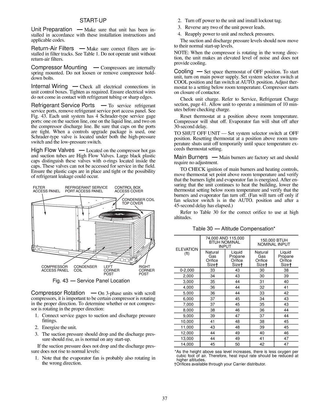
Refrigerant Service Ports — To service refrigerant service ports, remove refrigerant service port access panel. See Fig. 43. Each unit system has 4
High Flow Valves — Located on the compressor hot gas and suction tubes are High Flow Valves. Large black plastic caps distinguish these valves with
Fig. 43 — Service Panel Location
Compressor Rotation — On
1.Connect service gages to suction and discharge pressure fittings.
2.Energize the unit.
3.The suction pressure should drop and the discharge pres- sure should rise, as is normal on any
If the suction pressure does not drop and the discharge pres- sure does not rise to normal levels:
1.Note that the evaporator fan is probably also rotating in the wrong direction.
2.Turn off power to the unit and install lockout tag.
3.Reverse any two of the unit power leads.
4.Reapply power to unit and recheck pressures.
The suction and discharge pressure levels should now move to their normal
NOTE: When the compressor is rotating in the wrong direc- tion, the unit makes an elevated level of noise and does not provide cooling.
Cooling — Set space thermostat of OFF position. To start unit, turn on main power supply. Set system selector switch at COOL position and fan switch at AUTO. position. Adjust ther- mostat to a setting below room temperature. Compressor starts on closure of contactor.
Check unit charge. Refer to Service, Refrigerant Charge section, page 41. Allow unit to operate a minimum of 10 min- utes before checking charge.
Reset thermostat at a position above room temperature. Compressor will shut off. Evaporator fan will shut off after
TO SHUT OFF UNIT — Set system selector switch at OFF position. Resetting thermostat at a position above room tem- perature shuts unit off temporarily until space temperature ex- ceeds thermostat setting.
Main Burners — Main burners are factory set and should require no adjustment.
TO CHECK ignition of main burners and heating controls, move thermostat set point above room temperature and verify that the burners light and evaporator fan is energized. After en- suring that the unit continues to heat the building, lower the thermostat setting below room temperature and verify that the burners and evaporator fan turn off. (Fan will turn off only if fan selector switch is in the AUTO. position and after a
Refer to Table 30 for the correct orifice to use at high altitudes.
Table 30 — Altitude Compensation*
| 74,000 AND 115,000 | 150,000 BTUH | |||
| BTUH NOMINAL | ||||
| NOMINAL INPUT | ||||
| INPUT | ||||
ELEVATION |
|
| |||
(ft) | Natural | Liquid | Natural | Liquid | |
Gas | Propane | Gas | Propane | ||
| |||||
| Orifice | Orifice | Orifice | Orifice | |
| Size† | Size† | Size† | Size† | |
| 33 | 43 | 30 | 38 | |
2,000 | 34 | 43 | 30 | 39 | |
3,000 | 35 | 44 | 31 | 40 | |
4,000 | 36 | 44 | 32 | 41 | |
5,000 | 36 | 44 | 33 | 42 | |
6,000 | 37 | 45 | 34 | 43 | |
7,000 | 37 | 45 | 35 | 43 | |
8,000 | 38 | 46 | 36 | 44 | |
9,000 | 39 | 47 | 37 | 44 | |
10,000 | 41 | 48 | 38 | 45 | |
11,000 | 43 | 48 | 39 | 45 | |
12,000 | 44 | 49 | 40 | 46 | |
13,000 | 44 | 49 | 41 | 47 | |
14,000 | 45 | 50 | 42 | 47 | |
*As the height above sea level increases, there is less oxygen per cubic foot of air. Therefore, heat input rate should be reduced at higher altitudes.
†Orifices available through your Carrier distributor.
37