FRONT PANEL CONTROLS – CHANNEL CONTROL SECTION
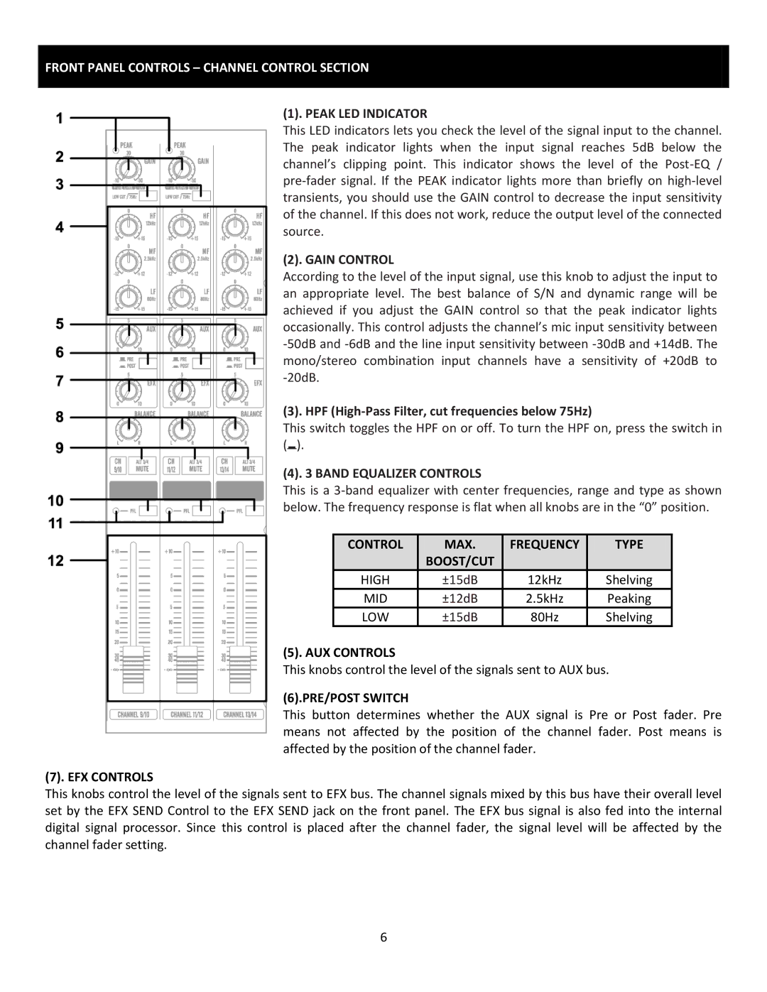
(1). PEAK LED INDICATOR
This LED indicators lets you check the level of the signal input to the channel. The peak indicator lights when the input signal reaches 5dB below the channel’s clipping point. This indicator shows the level of the
(2). GAIN CONTROL
According to the level of the input signal, use this knob to adjust the input to an appropriate level. The best balance of S/N and dynamic range will be achieved if you adjust the GAIN control so that the peak indicator lights occasionally. This control adjusts the channel’s mic input sensitivity between
(3). HPF
This switch toggles the HPF on or off. To turn the HPF on, press the switch in (![]() ).
).
(4). 3 BAND EQUALIZER CONTROLS
This is a
| CONTROL |
|
| MAX. |
|
| FREQUENCY |
|
| TYPE |
|
|
|
|
|
|
|
|
| ||||
|
|
|
| BOOST/CUT |
|
|
|
|
|
|
|
| HIGH |
|
| ±15dB |
|
| 12kHz |
|
| Shelving | |
| MID |
|
| ±12dB |
|
| 2.5kHz |
|
| Peaking | |
| LOW |
|
| ±15dB |
|
| 80Hz |
|
| Shelving | |
(5). AUX CONTROLS
This knobs control the level of the signals sent to AUX bus.
(6).PRE/POST SWITCH
This button determines whether the AUX signal is Pre or Post fader. Pre means not affected by the position of the channel fader. Post means is affected by the position of the channel fader.
(7). EFX CONTROLS
This knobs control the level of the signals sent to EFX bus. The channel signals mixed by this bus have their overall level set by the EFX SEND Control to the EFX SEND jack on the front panel. The EFX bus signal is also fed into the internal digital signal processor. Since this control is placed after the channel fader, the signal level will be affected by the channel fader setting.
6