FRONT PANEL CONTROLS – MAIN CONTROL SECTION (continued)
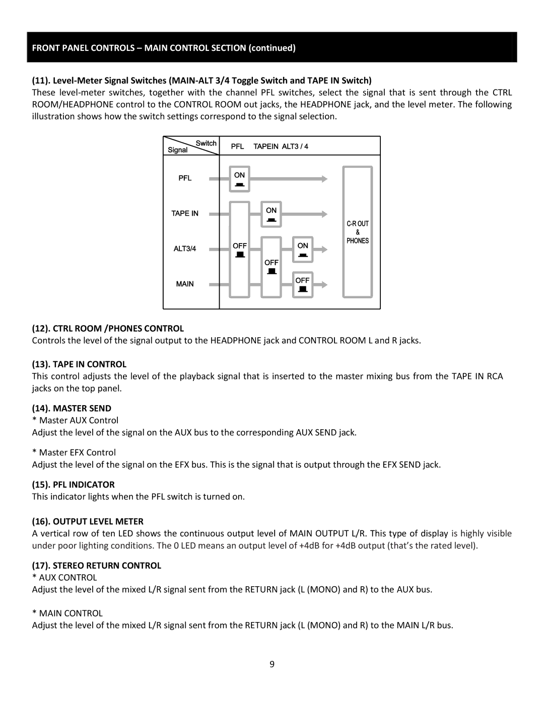
(11).
These
(12). CTRL ROOM /PHONES CONTROL
Controls the level of the signal output to the HEADPHONE jack and CONTROL ROOM L and R jacks.
(13). TAPE IN CONTROL
This control adjusts the level of the playback signal that is inserted to the master mixing bus from the TAPE IN RCA jacks on the top panel.
(14). MASTER SEND
* Master AUX Control
Adjust the level of the signal on the AUX bus to the corresponding AUX SEND jack.
* Master EFX Control
Adjust the level of the signal on the EFX bus. This is the signal that is output through the EFX SEND jack.
(15). PFL INDICATOR
This indicator lights when the PFL switch is turned on.
(16). OUTPUT LEVEL METER
A vertical row of ten LED shows the continuous output level of MAIN OUTPUT L/R. This type of display is highly visible under poor lighting conditions. The 0 LED means an output level of +4dB for +4dB output (that’s the rated level).
(17). STEREO RETURN CONTROL * AUX CONTROL
Adjust the level of the mixed L/R signal sent from the RETURN jack (L (MONO) and R) to the AUX bus.
* MAIN CONTROL
Adjust the level of the mixed L/R signal sent from the RETURN jack (L (MONO) and R) to the MAIN L/R bus.
9