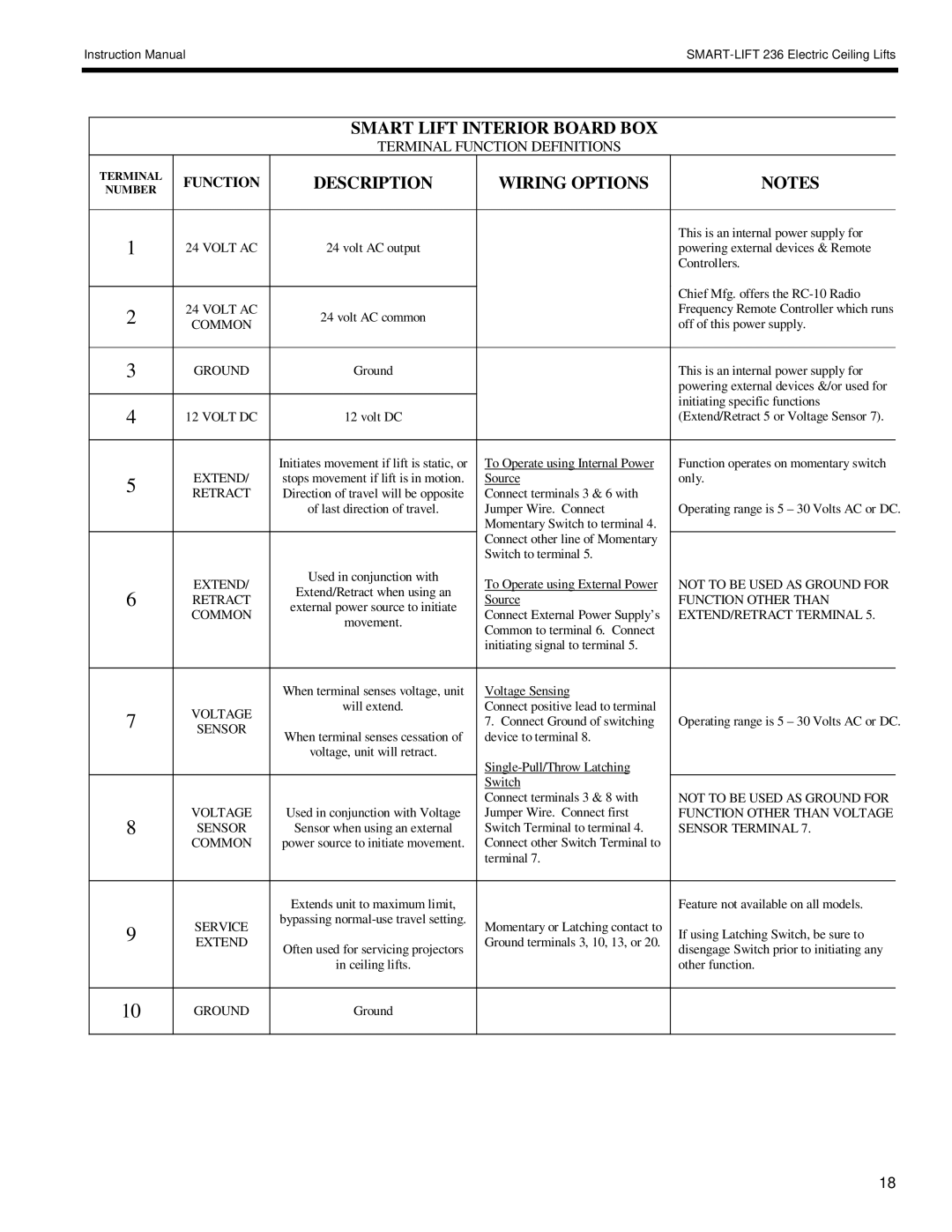
SL-236 specifications
The Chief Manufacturing SL-236 is a versatile and innovative solution designed to enhance the way we utilize space in various environments. This sturdy and stylish mounting system is ideal for displaying flat panel screens and is particularly well-suited for commercial and educational settings, as well as home theaters.One of the main features of the SL-236 is its exceptional build quality. Constructed from high-strength materials, this mount provides reliable support for a wide range of screen sizes, accommodating displays from 37 inches all the way up to 70 inches. The robust design ensures that the screens remain securely in place, reducing the risk of accidents or damage.
Another standout characteristic of the SL-236 is its extensive range of motion. The mount allows for tilt, pan, and lift adjustments, providing users with the flexibility to position their screens at the most optimal viewing angles. The effortless adjustment mechanisms enable quick reconfiguration for different settings or preferences, making it a user-friendly option for those who frequently adjust their display setups.
In addition to its functional attributes, the Chief Manufacturing SL-236 incorporates advanced technology to enhance performance. The mount is designed with integrated cable management solutions, keeping wires organized and minimizing clutter. This not only contributes to a cleaner aesthetic but also helps maintain the overall integrity and functionality of the display system.
Ease of installation is another significant advantage of the SL-236. The mount comes with a comprehensive installation guide and includes all necessary hardware, streamlining the process for end users. This ease of setup makes it an attractive option for both professional installers and DIY enthusiasts.
The SL-236 also boasts a sleek, modern design that can seamlessly blend into various environments. Its aesthetic appeal is complemented by its robust performance, making it a popular choice among users who prioritize both form and function.
In summary, the Chief Manufacturing SL-236 is a top-tier mounting solution that combines durability, flexibility, and user-friendly features. With its extensive range of motion, superior build quality, advanced cable management, and ease of installation, it stands out as an exemplary choice for anyone looking to optimize their viewing experience while ensuring safety and style. Whether for commercial, educational, or residential use, the SL-236 is a premier solution for modern display needs.

