Configuration for Two RAID Systems (AAMK36A2)
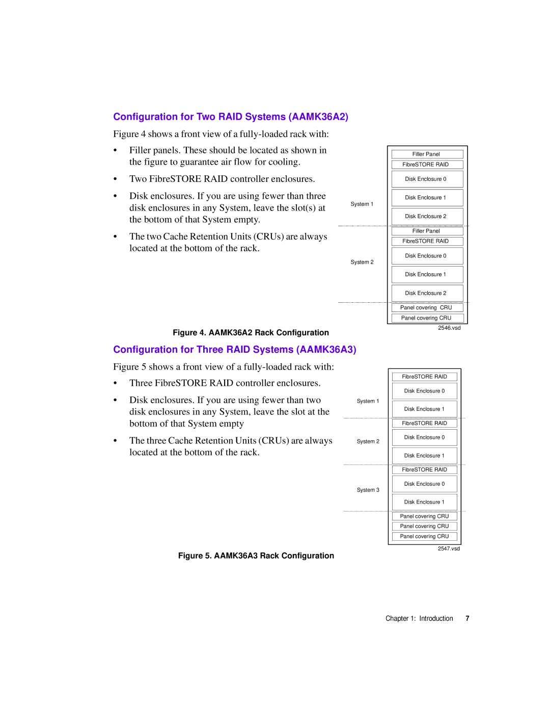
Figure 4 shows a front view of a fully-loaded rack with:
•Filler panels. These should be located as shown in the figure to guarantee air flow for cooling.
•Two FibreSTORE RAID controller enclosures.
•Disk enclosures. If you are using fewer than three
disk enclosures in any System, leave the slot(s) at |
| System 1 |
|
| |
the bottom of that System empty. |
|
|
•The two Cache Retention Units (CRUs) are always located at the bottom of the rack.
System 2
Figure 4. AAMK36A2 Rack Configuration
Configuration for Three RAID Systems (AAMK36A3)
Figure 5 shows a front view of a |
|
|
|
• Three FibreSTORE RAID controller enclosures. |
|
|
|
• Disk enclosures. If you are using fewer than two |
|
| System 1 |
disk enclosures in any System, leave the slot at the |
|
|
|
bottom of that System empty |
|
|
|
• The three Cache Retention Units (CRUs) are always |
|
|
|
|
| System 2 | |
located at the bottom of the rack. |
|
|
|
|
|
| |
|
|
|
|
|
|
|
|
|
|
| System 3 |
|
|
|
|
|
|
|
|
Figure 5. AAMK36A3 Rack Configuration
Filler Panel
FibreSTORE RAID
Disk Enclosure 0
Disk Enclosure 1
Disk Enclosure 2
Filler Panel
FibreSTORE RAID
Disk Enclosure 0
Disk Enclosure 1
Disk Enclosure 2
Panel covering CRU
Panel covering CRU
2546.vsd
FibreSTORE RAID
Disk Enclosure 0
Disk Enclosure 1
FibreSTORE RAID
Disk Enclosure 0
Disk Enclosure 1
FibreSTORE RAID
Disk Enclosure 0
Disk Enclosure 1
Panel covering CRU
Panel covering CRU
Panel covering CRU
2547.vsd
Chapter 1: Introduction | 7 |
