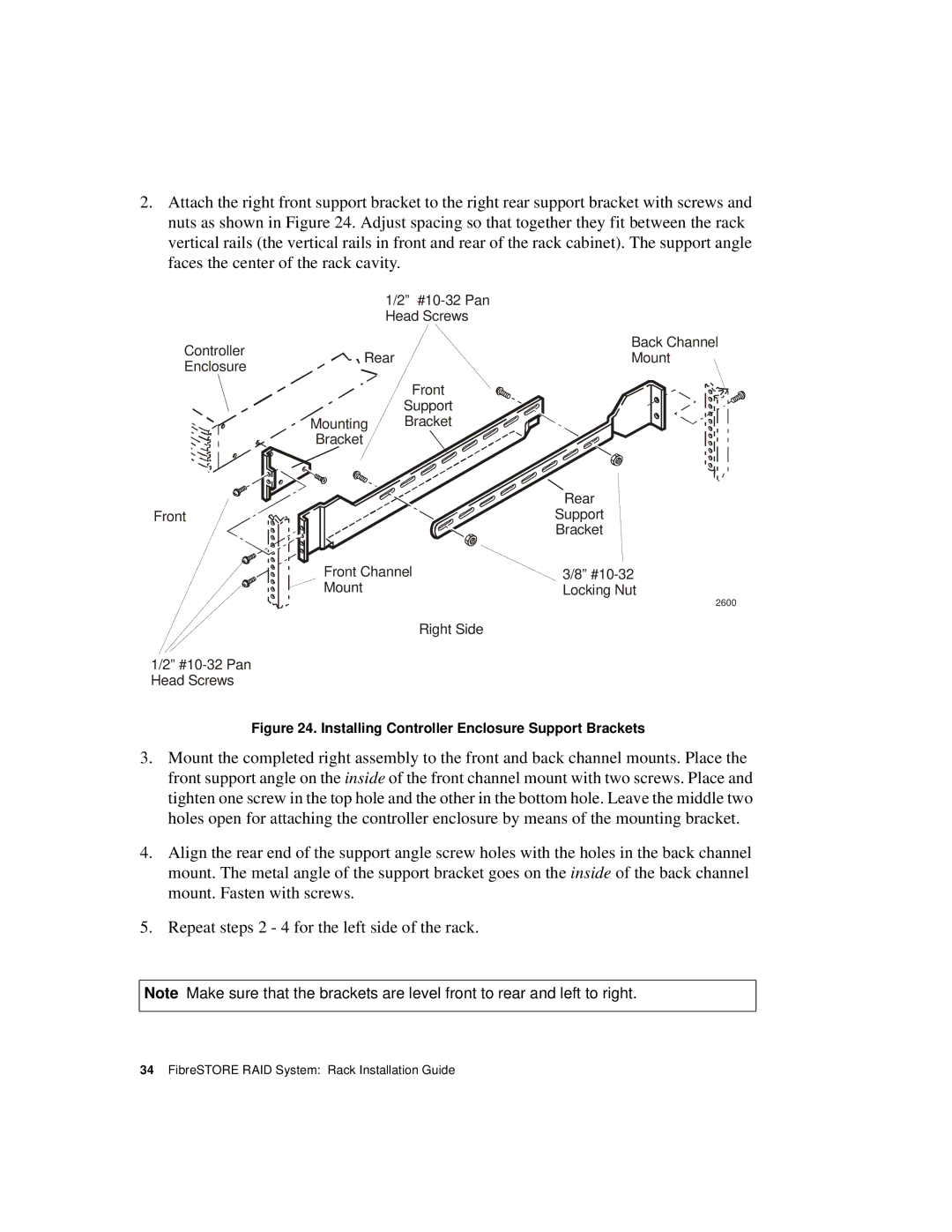
2.Attach the right front support bracket to the right rear support bracket with screws and nuts as shown in Figure 24. Adjust spacing so that together they fit between the rack vertical rails (the vertical rails in front and rear of the rack cabinet). The support angle faces the center of the rack cavity.
1/2”
Head Screws
Controller |
| Back Channel | |
Rear | Mount | ||
Enclosure | |||
|
| ||
|
| Front | |
|
| Support | |
| Mounting | Bracket | |
| Bracket |
|
Front
1/2”
| Rear |
| Support |
| Bracket |
Front Channel | 3/8” |
Mount | Locking Nut |
| 2600 |
| Right Side |
Figure 24. Installing Controller Enclosure Support Brackets
3.Mount the completed right assembly to the front and back channel mounts. Place the front support angle on the inside of the front channel mount with two screws. Place and tighten one screw in the top hole and the other in the bottom hole. Leave the middle two holes open for attaching the controller enclosure by means of the mounting bracket.
4.Align the rear end of the support angle screw holes with the holes in the back channel mount. The metal angle of the support bracket goes on the inside of the back channel mount. Fasten with screws.
5.Repeat steps 2 - 4 for the left side of the rack.
Note Make sure that the brackets are level front to rear and left to right.
