Catalyst 2960 Switch Hardware Installation Guide
Catalyst 2960 Switch Hardware Installation Guide
N T E N T S
Rack-Mounting2-8 Removing Screws from the Switch
Console Port A-4
Starting the Terminal Emulation Software
Purpose
Audience
Conventions
For information about related products, see these documents
Related Documentation
Preface
Preface Catalyst 2960 Switch Hardware Installation Guide
Product Overview
Features
1000BASE-CWDM
These sections describe the switch front panels
Catalyst 2960 Switch 24- and 48-Port Switches
Front Panel Description
10/100 ports Dual-purpose ports
Catalyst 2960-24-S, 2960-24TC-S, and 2960-48TC-S Switches
10/100 ports 2 Dual-purpose ports
Catalyst 2960-24TC-L Switch Front Panel
10/100 ports
Catalyst 2960G-24TC-L and Catalyst 2960G-48TC-L Switches
10/100 ports 2 10/100/1000 uplink ports
10/100/1000 ports 2 Dual-purpose ports
Catalyst 2960 Switch 8-Port Switches
Catalyst 2960PD-8TT-L Switch
These sections describe the Catalyst 2960 8-port switches
10/100 Ports
Catalyst 2960-8TC-L Catalyst 2960G-8TC -L Switches
Console port Dual-purpose port 10/100/1000 ports
PoE Ports
10/100/1000 Ports
SFP Module Slots
Dual-Purpose Port
Power Input Port Catalyst 2960PD-8TT-L Switch
10/100/1000 Port
LEDs
16 Connecting Through an External AC Power Adapter
Status LED Port LEDs Duplex LED
Mode button
System LED
Speed LED
Port LEDs and Modes
Port status Port status. This is the default mode
Port speed Port operating speed 10, 100, or 1000 Mb/s
Port Mode LED Color Meaning
Meaning of Port LED Colors in Different Modes on the Switch
Dual-Purpose Port LEDs
Rear Panel Description
Internal Power Supply Connector
Power Supplies
Cisco RPS Connectors
Console Port
Cisco RPS 2300 Connector
Security Slots
Management Options
Security slot
Network Configurations
OL-7075-05
Preparing for Installation
Switch Installation 24- and 48-Port Switches
This section covers these topics
PWR-RPS2300, PWR675-AC-RPS-N1=. Statement
Statement 371-Power Cable and AC Adapter
Guidelines for Particulate Matter
Installation Guidelines
Verifying Package Contents
Verifying Switch Operation
Installing the Switch
Rack-Mounting
Removing Screws from the Switch
Phillips flat-head screws
Attaching Brackets to the Catalyst 2960 Switch
137076
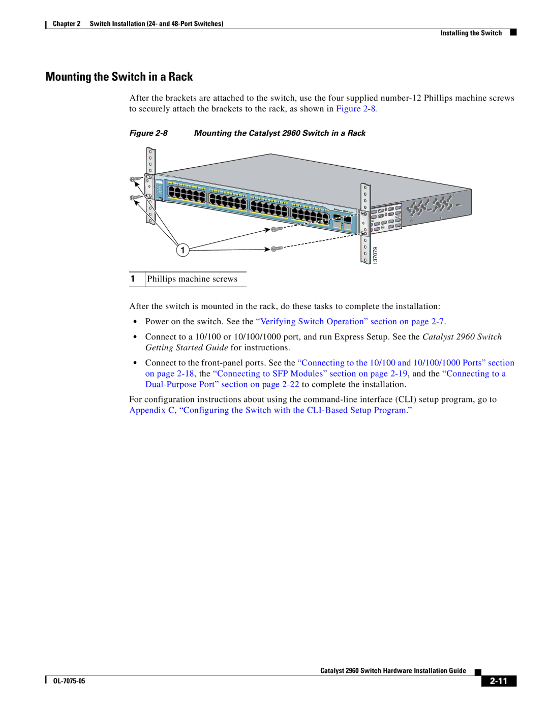
Phillips machine screws
Mounting the Switch in a Rack
Attaching the Cable Guide
Wall-Mounting
Cable guide screw
Phillips truss-head screws
Attaching the Brackets to the Switch for Wall-Mounting
Attaching the RPS Connector Cover
Phillips pan-head screws RPS connector RPS connector cover
User-supplied screws
Mounting the Switch on a Wall
Table- or Shelf-Mounting
Installing and Removing SFP Modules
13 SFP Module with a Bale-Clasp Latch
Installing SFP Modules into SFP Module Slots
SFP module
Removing SFP Modules from SFP Module Slots
Connecting to the 10/100 and 10/100/1000 Ports
16 Connecting to an Ethernet Port
Connecting to SFP Modules
17 Connecting to a Fiber-Optic SFP Module Port
Connecting to Fiber-Optic SFP Modules
18 Connecting to a 1000BASE-T SFP Module
Connecting to 1000BASE-T SFP Modules
Where to Go Next
Connecting to a Dual-Purpose Port
Start an Snmp application such as the CiscoView application
OL-7075-05
Switch Installation 8-Port Switches
Statement 371-Power Cable and AC Adapter
Installation Guidelines
Equipment That You Supply
Verifying Package Contents
Desk- or Shelf-Mounting without Mounting Screws
Verifying Switch Operation
Desk- or Shelf-Mounting with Mounting Screws
Installing the Mounting Screws on Top of a Desk or Shelf
Under the Desk- or Shelf-Mounting with Mounting Screws
Mounting the Switch on Top of a Desk or Shelf
Desk or shelf Screws Screw template Adhesive
Installing the Mounting Screws Under a Desk or Shelf
Desk or shelf Slides on this way Screws
Mounting the Switch Under a Desk or Shelf
Wall Screw template Screws
Wall-Mounting with Mounting Screws
Installing the Switch On a Wall
Switch 3 Slides on this way Screw
Magnet
Magnet Mounting
Phillips flat-head screw
Attaching Brackets to the Switch
Wall-Mounting with Rack-Mount Brackets
Mounting the Switch in a 19-Inch Rack
10 Mounting the Switch on a Wall
Switch Installation 8-Port Switches Where to Go Next
This section includes these troubleshooting topics
Diagnosing Problems
Bad or Damaged Cable
Verify Switch Post Results
Monitor Switch LEDs
Verify Switch Connections
Link Status
Transceiver Module Port Issues
Port and Interface Settings
Ethernet and Fiber Cables
Speed, Duplex, and Autonegotiation
Monitor Switch Performance
Ping the End Device
Spanning Tree Loops
Autonegotiation and NIC Cards
Clearing the Switch IP Address and Configuration
Cabling Distance
Cisco 11-character label
Locating the Switch Serial Number
200186
OL-7075-05
Connecting to 10BASE-T- and 100BASE-TX-Compatible Devices
Connector Specifications
3 4 5 6 7
Connecting to 1000BASE-T Devices
Dual-Purpose Ports
SFP Module Ports
SFP Module Cable Specifications
Cable and Adapter Specifications
50/125 500 Feet 2 km GLC-GE-100FX 62.5/125
1310 TX
652 32,810 feet 10 km GLC-FE-100BX-D 1550 RX GLC-FE-100BX-U
1310
Four Twisted-Pair Cable Pinouts for 1000BASE-T Ports
Two Twisted-Pair Cable Pinouts
Identifying a Crossover Cable
Crossover Cable and Adapter Pinouts
TxD RxD
Adapter Pinouts
RxD TxD
Technical Specifications
Power Requirements
Physical Dimensions
Power Requirements
Accessing the CLI Through Express Setup
Accessing the CLI
Accessing the CLI Through the Console Port
Connecting to the Console Port
Starting the Terminal Emulation Software
Figure C-1 Connecting a Switch to a PC
Entering the Initial Configuration Information
Connecting to a Power Source
IP Settings
Completing the Setup Program
These choices appear
Catalyst 2960 Switch Hardware Installation Guide OL-7075-05
OL-7075-05
Cable guide, attaching Cable lengths
AC power Connecting to
Connector Specifications
AC power adapter for Catalyst 2960PD-8TT-L switch
Connectors and cables 10/100/1000 A-1 to A-2 Console
Accessing by using Express Setup C-1
Connecting to the console port
Connection procedures
LEDs Color meanings
PoE Port mode
System Troubleshooting with Lightning activity warning
No user-serviceable parts warning
See also Mode button Description
High-powered devices
On Catalyst 2960-24PC-L and 24LT-L switches
Port and interface troubleshooting Rack-mounting warning
Shelf-mounting
Attachment warning 1-19,2-2,2-7connecting to 2-7,3-6
Safety warnings
Connectors Described Installation
Trained and qualified personnel
Read the wall-mounting instructions