Chapter 3 Installing the AVS 3120
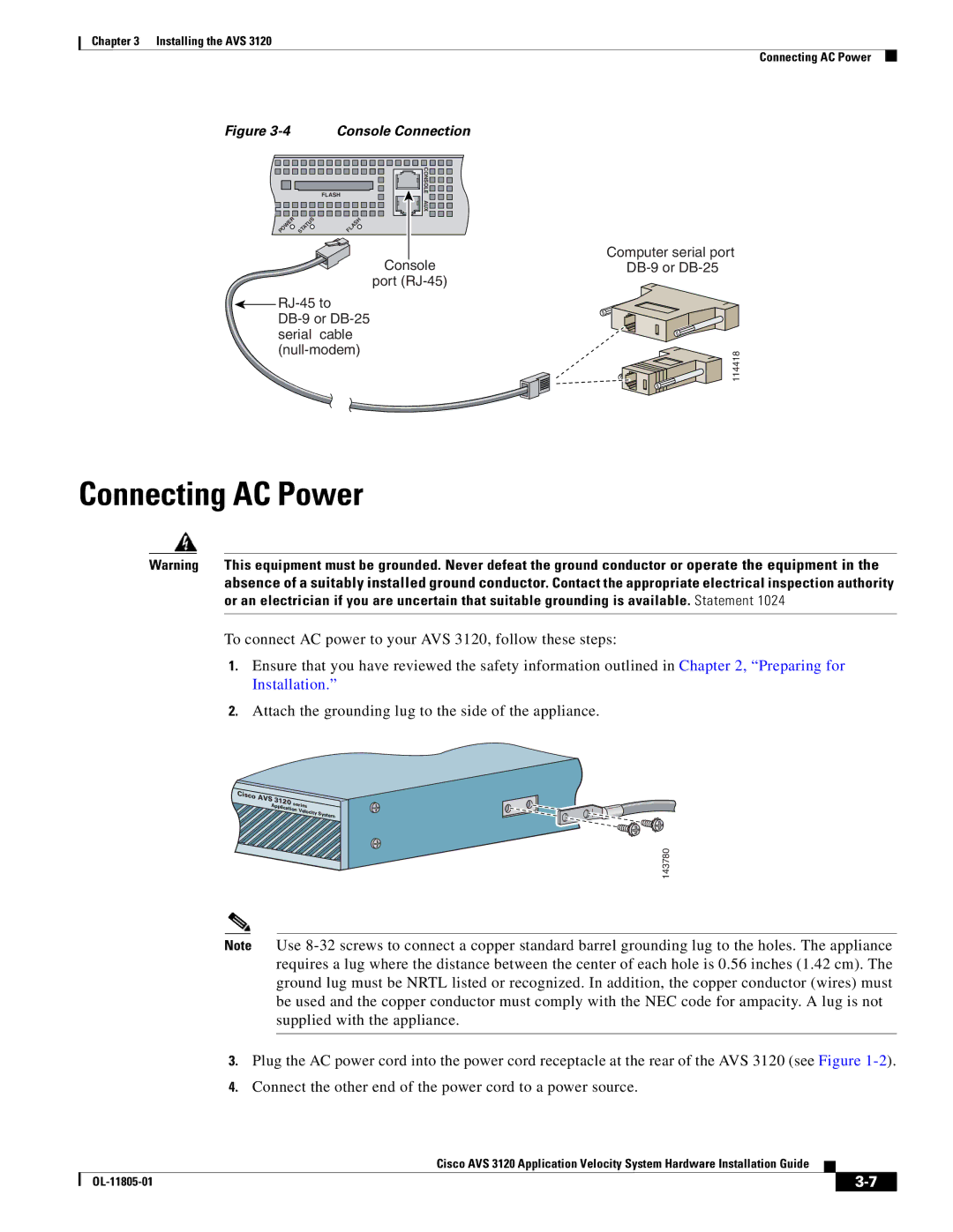
Figure 3-4 Console Connection
FLASH | CONSOLE |
| |
| AUX |
POWER STATUS | FLASH |
Console
port
![]()
Connecting AC Power
Computer serial port
114418
Connecting AC Power
Warning | This equipment must be grounded. Never defeat the ground conductor or operate the equipment in the |
| absence of a suitably installed ground conductor. Contact the appropriate electrical inspection authority |
| or an electrician if you are uncertain that suitable grounding is available. Statement 1024 |
|
|
To connect AC power to your AVS 3120, follow these steps:
1.Ensure that you have reviewed the safety information outlined in Chapter 2, “Preparing for Installation.”
2.Attach the grounding lug to the side of the appliance.
Cisco
AV |
|
|
S 3 | 120 | series |
Applica | ||
| tion | |
|
| Velocity |
|
| Sys |
|
| tem |
143780
Note Use
3.Plug the AC power cord into the power cord receptacle at the rear of the AVS 3120 (see Figure
4.Connect the other end of the power cord to a power source.
Cisco AVS 3120 Application Velocity System Hardware Installation Guide
|
| ||
|
|