Chapter 2 Setting Up Your Cisco Unified Videoconferencing 3515 MCU
Verifying the Package Contents
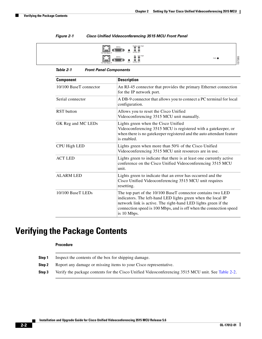
Figure 2-1 Cisco Unified Videoconferencing 3515 MCU Front Panel
| SERIAL | GK Reg CPU Hight |
|
| |
10/100 Base T | RST | ALARM ACT |
|
| |
| SERIAL | MC CPU Hight |
| PWR | |
|
| |
10/100 Base T | RST | ALARM ACT |
|
|
Table
157265
Component | Description |
|
|
10/100 BaseT connector | An |
| for the IP network port. |
|
|
Serial connector | A |
| configuration. |
|
|
RST button | Allows you to reset the Cisco Unified |
| Videoconferencing 3515 MCU unit manually. |
|
|
GK Reg and MC LEDs | Lights green when the Cisco Unified |
| Videoconferencing 3515 MCU is registered with a gatekeeper, or |
| when there is no gatekeeper registered and the auto attendant feature |
| is enabled. |
|
|
CPU High LED | Lights green when more than 50% of the Cisco Unified |
| Videoconferencing 3515 MCU unit resources are in use. |
|
|
ACT LED | Lights green to indicate that there is at least one currently active |
| conference on the Cisco Unified Videoconferencing 3515 MCU |
| unit. |
|
|
ALARM LED | Lights green to indicate that an error has occurred and the |
| Cisco Unified Videoconferencing 3515 MCU unit requires |
| resetting. |
|
|
10/100 BaseT LEDs | The top part of the 10/100 BaseT connector contains two LED |
| indicators. The |
| network link is active. The |
| connection speed is 100 Mbps, and is off when the connection speed |
| is 10 Mbps. |
|
|
Verifying the Package Contents
Procedure
Step 1 Inspect the contents of the box for shipping damage.
Step 2 Report any damage or missing items to your Cisco representative.
Step 3 Verify the package contents for the Cisco Unified Videoconferencing 3515 MCU unit. See Table
Installation and Upgrade Guide for Cisco Unified Videoconferencing 3515 MCU Release 5.6
| ||
|