Cisco Secure Router 520 Series Software Configuration Guide
Americas Headquarters
Page
N T E N T S
Iii
Verify the Configuration
Additional Configuration Options
Reference Information
Rsvp
Vii
Using the Tftp Download Command C-5
Viii
Audience
Preface
Objective
Part 2 Configuring Your Router for Ethernet and DSL Access
Part 3 Configuring Additional Features and Troubleshooting
Organization
Part 1 Getting Started
Conventions
Appendix D, Common Port Assignments
Warnung Wichtige Sicherheitshinweise
Avvertenza Importanti Istruzioni Sulla Sicurezza
Aviso Instruções Importantes DE Segurança
Xii
Guarde Estas Instrucciones
Xiii
GEM Disse Anvisninger
Xiv
Page
Cisco Regulatory Compliance and Safety Information Roadmap
Cisco Secure Router 520 Series Hardware Installation Guide
Related Documentation
Xvi
Obtaining Documentation and Submitting a Service Request
Xvii
Xviii
Getting Started
Page
Basic Router Configuration
Viewing the Default Configuration
Information Needed for Customizing the Default Parameters
Router Interface Port Label
Configuring Basic Parameters
Interface Port Labels
Configure Global Parameters
Configure Fast Ethernet LAN Interfaces
Configure WAN Interfaces
Command Purpose
Routerconfig# interface fastethernet
Routerconfig-if# ip address 255.255.255.0
Interface type number
No shutdown
Configure the Wireless Interface
Configuring a Loopback Interface
Enables the ATM 0 interface
Exits configuration mode for the ATM interface
Exits configuration mode for the loopback
Interface and returns to global configuration mode
Loopback interface
Router# show interface loopback
Configuring Command-Line Access to the Router
Password password
Login
Exec-timeoutminutes seconds
End
Verifying Your Configuration
Configuring Static Routes
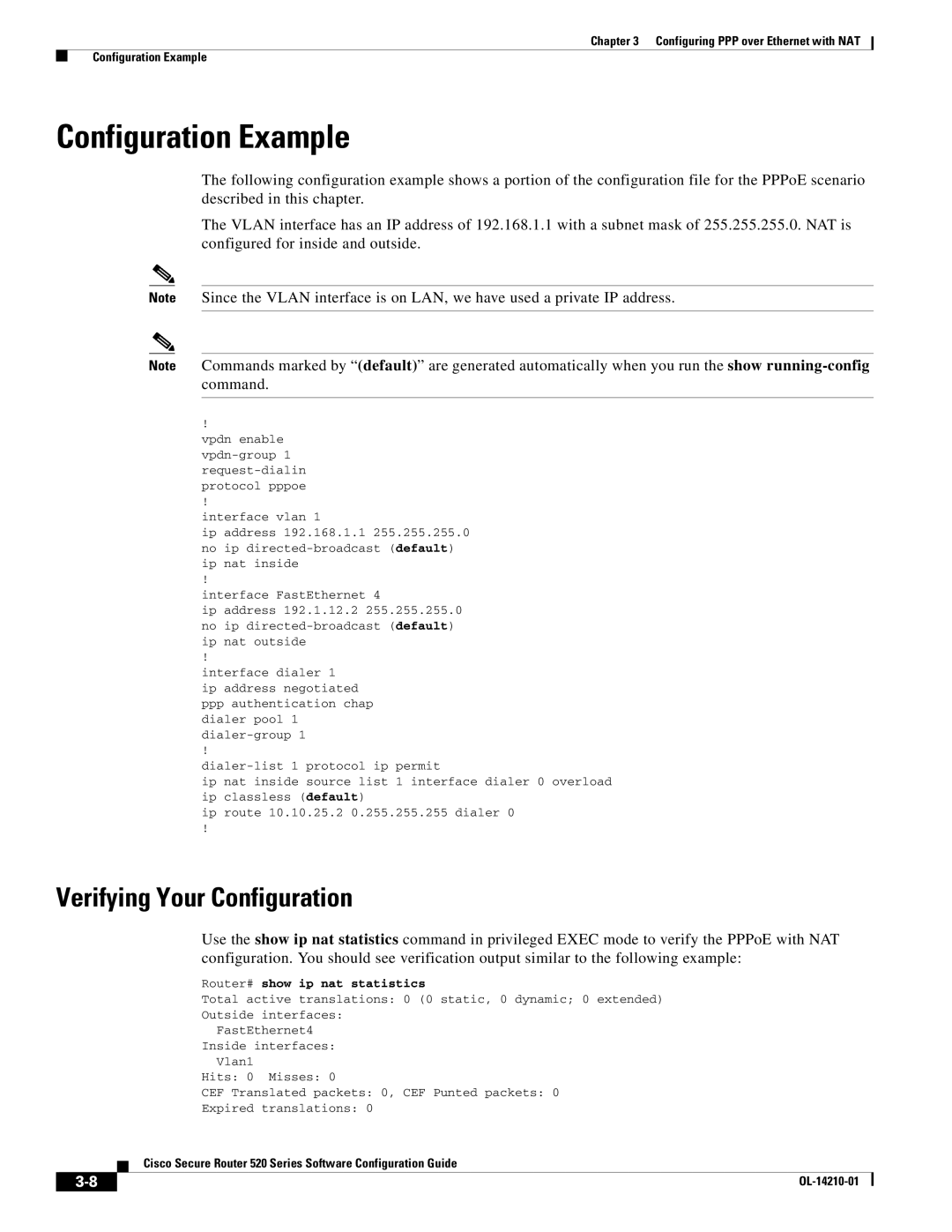
Configuration Example
Configuring Dynamic Routes
Configuring RIP
Command Task
Router rip
No auto-summary
Configuring Your Router for Ethernet and DSL Access
Page
For DSL-Based Network Deployments
Sample Network Deployments
For Ethernet-Based Network Deployments
Sample Network Deployments
Configuring PPP over Ethernet with NAT
PPPoE session between the client and a PPPoE server
Configuration Tasks
Command or Action Purpose
Vpdn enable
PPPoE
Configure the Fast Ethernet WAN Interfaces
Configures the PPPoE client and specifies
Request-dialin
Protocol l2tp pppoe
Configure the Dialer Interface
Configure Network Address Translation
Ppp authentication protocol1 protocol2
Dialer pool number
Dialer-group group-number
Enables dynamic translation of addresses on
By the access list 1 to be translated to one
Permitted by access list acl1 to be translated to one
Enables the configuration changes just made to
Access-list access-list-number deny permit
Routerconfig# access-list 1 permit
Ip nat inside outside
Source source-wildcard
Configuration Example
Router# show ip nat statistics
Id 1 access-list 1 interface Dialer0 refcount Queued Packets
OL-14210-01
Configuring PPP over ATM with NAT
PPP over ATM with NAT
PPPoA
Sets the PPP authentication method
Authentication Protocol Chap
Using a dialer group controls access to
Specifies that the IP address for the dialer
Command Reference, Volume 1 of 4 Routing
Configure the ATM WAN Interface
Configure DSL Signaling Protocol
Configuring Adsl
Attribute Description Default Value
Dsl lom integer Dsl enable-training-log
Pool1
Permitted by access list acl1 to be translated to
One of the addresses specified in the NAT pool
Reference, Volume 1 of 4 Addressing
0.255
ATM0
Configuring a LAN with Dhcp and VLANs
Dhcp
Dotted-decimal domain name
Configure Dhcp
VLANs
Enters Dhcp pool configuration mode. The name
Exits Dhcp configuration mode, and enters
Global configuration mode
Creates a Dhcp address pool on the router
Verify Your Dhcp Configuration
Router# show ip dhcp import
Ip dhcp pool
Server statistics
Vlan vlan-id media type name vlan-name
Configure VLANs
Vlan database
Assign a Switch Port to a Vlan
Verify Your Vlan Configuration
Exits interface mode and returns to privileged
Exec mode
Router# show vlan-switch
Vlan
Said MTU
Configuring a VPN Using Easy VPN and an IPsec Tunnel
Remote Access VPN Using IPsec Tunnel
Cisco Easy VPN
Configure the IKE Policy
Configure Group Policy Information
Apply Mode Configuration to the Crypto Map
Enable Policy Lookup
Configure IPsec Transforms and Protocols
Configure the IPsec Crypto Method and Parameters
Apply the Crypto Map to the Physical Interface
Reverse-route
Crypto map map-name seq-num ipsec-isakmp
Dynamic dynamic-map-name discover
Create an Easy VPN Remote Configuration
Crypto map map-name
Verifying Your Easy VPN Configuration
Crypto ipsec client ezvpn name outside inside
Ezvpn ezvpnclient outside
Router# show crypto ipsec client ezvpn
Crypto ipsec client ezvpn ezvpnclient connect auto
OL-14210-01
Site-to-Site VPN Using an IPsec Tunnel and GRE
VPNs
Configure a VPN
GRE Tunnels
Configure the IKE Policy
Configure Group Policy Information
Ip local pool default poolname
Domain name
Low-ip-address high-ip-address
Enable Policy Lookup
Configure IPsec Transforms and Protocols
Creates a dynamic crypto map entry, and enters
Configure the IPsec Crypto Method and Parameters
Specifies global lifetime values used when
Apply the Crypto Map to the Physical Interface
Map
Configure a GRE Tunnel
192.168.101.1
Tunnel interface must be configured to
Exits interface configuration mode, and returns to
Enters ACL configuration mode for the named
Access-list-name ACL that is used by the crypto map
Set transform-set set1 match address
No cdp run
OL-14210-01
Configuring a Simple Firewall
Fast Ethernet LAN interface the inside interface for NAT
Configure Access Lists
Creates an access list which prevents Internet
Details about this command
Creates an access list that allows network traffic
Configure Inspection Rules
Apply Access Lists and Inspection Rules to Interfaces
Routerconfig-if# ip access-group 103
Ip nat outside no cdp enable
Configuring a Wireless LAN Connection
1shows a wireless network deployment
Configure the Root Radio Station
For clients
Equivalent Privacy WEP cannot use
Bridges for more details
Creates a Service Set ID SSID, the public
Name of a wireless network
Sets the permitted authentication methods for a
User attempting access to the wireless LAN
Configure Bridging on VLANs
Bridge-group parameter
Configure Radio Station Subinterfaces
Bridge-group number
Disables the Cisco Discovery Protocol CDP
On the wireless interface
Enabled, the following commands are
Automatically enabled, and cannot be
No bridge-group 2 unicast-flooding
No ip address bridge-group
Configuring Additional Features and Troubleshooting
Page
Additional Configuration Options
10-1
10-2
11-1
Configuring Security Features
Authentication, Authorization, and Accounting
Configuring AutoSecure
Configuring Access Lists
Configuration Commands
ACL Type
Configuring a Cbac Firewall
Access Groups
Ip access-groupaccess-list-number access-list-nameinout
Ip inspect name inspection-name protocol timeout seconds
11-4
Configuring Cisco IOS Firewall IDS
Configuring VPNs
Troubleshooting
Getting Started
Before Contacting Cisco or Your Reseller
12-1
Adsl Troubleshooting
ATM Troubleshooting Commands
Ping atm interface Command
12-2
Show interface Command
12-3
12-4
Shutdown command
Output Cause
Show atm interface Command
Debug atm Commands
Field Description
12-5
Router# debug atm events Router#
Router# debug atm errors ATM errors debugging is on Router#
12-6
12-7
Example 12-6 Viewing ATM Interface Processor Events-Failure
Router# debug atm packet Router# 012348ATM0O
Software Upgrade Methods
12-8
Recovering a Lost Password
Change the Configuration Register
12-9
Router# show version
12-10
Rommon 2 confreg
Reset the Password and Save Your Changes
Reset the Configuration Register Value
Router# show startup-config
Router# copy running-config startup-config
12-12
Reference Information
Page
PC Operating System Software
Configuring the Router from a PC
Cisco IOS Software Basic Skills
Understanding Command Modes
As interface atm
Ctrl-Z
Router rip, from
Enable Secret Passwords and Enable Passwords
Getting Help
Entering Global Configuration Mode
Using Commands
Saving Configuration Changes
Abbreviating Commands
Undoing Commands
Command-Line Error Messages
Where to Go Next
Summary
OL-14210-01
Concepts
Adsl
Network Protocols
Routing Protocol Options
PPP Authentication Protocols
PAP
ATM for DSL
Network Interfaces
Ethernet
Dialer Interface
PVC
Easy IP Phase
PPP Fragmentation and Interleaving
QoS
IP Precedence
Cbwfq
Low Latency Queuing
Access Lists
OL-14210-01
Configure terminal Enters global configuration mode
Config-reg Resets the configuration register
ROM Monitor
Entering the ROM Monitor
ROM Monitor Commands
Reload
Command Description
Command Descriptions
Disaster Recovery with Tftp Download
Tftp Download Command Variables
Variable Command
Configuration Register
Using the Tftp Download Command
TFTPTIMEOUT= time
Retrytimes
Rommon 1 confreg
Changing the Configuration Register Manually
Changing the Configuration Register Using Prompts
Xmodem -cyrxdestinationfilename
Command Description
Console Download
Debug Commands
Error Reporting
Exiting the ROM Monitor
Appendix C ROM Monitor Exiting the ROM Monitor
OL-14210-01
Common Port Assignments
Port Keyword Description
Finger
See ARP
See Adsl
See AAL
See ATM
See CAR
IN-2
See Dhcp
IN-3
See LCP
IN-4
IN-5
IN-6
See RIP
See NAT
IN-7
IN-8