Chapter 7 PIX 535
Installing a Circuit Board in the PIX 535
Circuit Board Slot Description
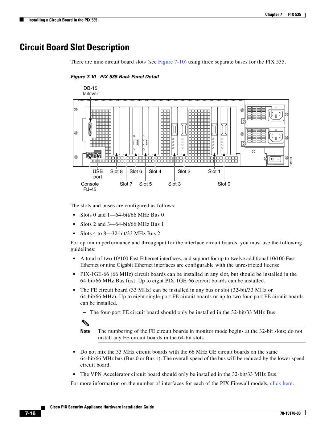
There are nine circuit board slots (see Figure
Figure 7-10 PIX 535 Back Panel Detail
failover
61919 |
USB | Slot 8 Slot 6 Slot 4 | Slot 2 | Slot 1 |
port |
|
|
|
Console | Slot 7 Slot 5 | Slot 3 | Slot 0 |
|
|
|
The slots and buses are configured as follows:
•Slots 0 and
•Slots 2 and
•Slots 4 to
For optimum performance and throughput for the interface circuit boards, you must use the following guidelines:
•A total of two 10/100 Fast Ethernet interfaces, and support for up to twelve additional 10/100 Fast Ethernet or nine Gigabit Ethernet interfaces are configurable with the unrestricted license
•
•The FE circuit board (33 MHz) can be installed in any bus or slot
–The
Note The numbering of the FE circuit boards in monitor mode begins at the
•Do not mix the 33 MHz circuit boards with the 66 MHz GE circuit boards on the same
•The VPN Accelerator circuit board should only be installed in the
For more information on the number of interfaces for each of the PIX Firewall models, click here.
Cisco PIX Security Appliance Hardware Installation Guide
| ||
|