Cisco Systems user service Attaching a Grounding Lug to the PIX 535 DC

Models: 535

1 24
Download 24 pages 25.83 Kb
Page 22
Image 22

Chapter 7 PIX 535

Installing the PIX 535 DC Model

Step 3 Terminate the DC input wiring on a DC source capable of supplying at least 15 amps. A 15-amp circuit breaker is required at the -48 VDC facility power source. An easily accessible disconnect device should be incorporated into the facility wiring.

Step 4 Be sure the PIX 535 power is off by checking the power switch at the rear of the unit.

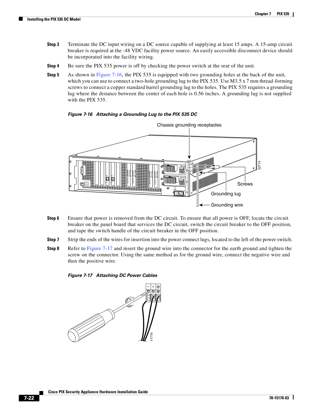
Step 5 As shown in Figure 7-16, the PIX 535 is equipped with two grounding holes at the back of the unit, which you can use to connect a two-hole grounding lug to the PIX 535. Use M3.5 x 7 mm thread-forming screws to connect a copper standard barrel grounding lug to the holes. The PIX 535 requires a grounding lug where the distance between the center of each hole is 0.56 inches. A grounding lug is not supplied with the PIX 535.

Figure 7-16 Attaching a Grounding Lug to the PIX 535 DC

Chassis grounding receptacles


STATUS

Ð

+


STATUS

Ð

+

Screws

Grounding lug

Grounding wire

52714

Step 6 Ensure that power is removed from the DC circuit. To ensure that all power is OFF, locate the circuit breaker on the panel board that services the DC circuit, switch the circuit breaker to the OFF position, and tape the switch handle of the circuit breaker in the OFF position.

Step 7 Strip the ends of the wires for insertion into the power connect lugs, located to the left of the power switch.

Step 8 Refer to Figure 7-17and insert the ground wire into the connector for the earth ground and tighten the screw on the connector. Using the same method as for the ground wire, connect the negative wire and then the positive wire.

Figure 7-17 Attaching DC Power Cables

– +

11779

Cisco PIX Security Appliance Hardware Installation Guide

7-22

78-15170-03


Page 22
Image 22
Cisco Systems user service Attaching a Grounding Lug to the PIX 535 DC