Contents
Cisco 800 Series Routers Hardware Installation Guide
Page
Cisco 800 Series Routers Hardware Installation Guide
Page
N T E N T S
Mounting on a Table
Audience
Organization
Conventions
Vii
Viii
Obtaining Documentation
Cisco.com
Documentation DVD
Ordering Documentation
Cisco Product Security Overview
Reporting Security Problems in Cisco Products
Documentation Feedback
Obtaining Technical Assistance
Cisco Technical Support Website
Submitting a Service Request
Definitions of Service Request Severity
Obtaining Additional Publications and Information
Xii
Xiii
Xiv
Overview
Feature Summary
Feature Routers Description
Router Ethernet Ports Isdn Ports Telephone Ports
Router Ports Summary
Front Panels
Back Panels
Link LED Ethernet port Isdn BRI S/T port
Cisco 802 Router Back Panel
Cisco 804 Router Back Panel
LEDs
Color Function
CH1
CH1 RXD
CH1 TXD
CH2
Installation
Safety
European Union Statements
Isdn S/T Ports Statement
Preventing Electrostatic Discharge Damage
Network Termination Point Statement
Unpacking Your Router
Preinstallation Activities
Preventing Router Damage
Installing Your Router
Connecting Ethernet Devices
Network
Device
Network Device Ethernet Cable
Connected to Router Router Port Type Button Setting
Connecting Hubs
Connecting a Server, PC, or Workstation
Connecting an Isdn Line
Connecting an Isdn Line to Cisco 801 and Cisco 803 Routers
NT1
Connecting an Isdn Line to Cisco 802 and Cisco 804 Routers
Connecting an Idsl Line
Isdn
Connecting a Digital Telephone
Connecting the Idsl Cable to Cisco Idsl Routers
Connecting an Analog Telephone, Fax, or Modem
Vendor Name Product Name For More Information
Connecting a Terminal or PC
Connecting Terminal or PC
Mounting on a Table
Connecting the Power Supply
Mounting Your Router
Mounting on a Wall
11 Wall-Mounting Brackets Bottom of Router
Verifying Installation
Installation Verifying Installation
Power/Link LEDs To Check Normal Patterns
Where to Go from Here
Troubleshooting
Problems During First Startup
Symptom Problem Solutions
Problems After First Startup
Symptom
To HUB/TO PC
LINE, CH1, CH1 RXD
Correctly, see the Connecting a Digital
Problems After Router Is Running
CH1, CH1 RXD, CH1 TXD
CH1 RXD, CH1 TXD, CH2
When Contacting Your Cisco Reseller
Page
Isdn and Idsl Concepts
Page
System Specifications
Description Design Specification
Port Connector Pinouts
TX+ RX+
Button OUT Pin Position
RX+ TX+
Button Pin OUT Position
Pin Function
RTS DTR TXD GND RXD DSR CTS
TXD+ RXD+
Tip
Cabling Specifications
ROF RTN
Ethernet Cable Specifications
Maximum Cable Distances
Type Category Shielding
10BASE-T
Page
Numerics
GL-1
GL-2
GL-3
GL-4
D E
IN-1
Modem, connecting Mounting the router
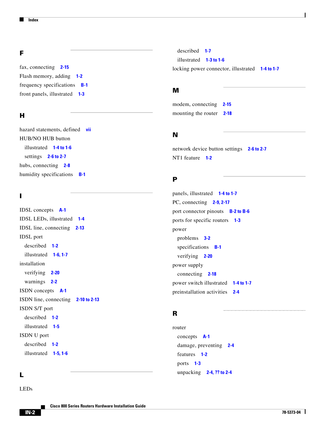
IN-2
Illustrated Settings Troubleshooting
IN-3
IN-4

