Chapter 2 Installation
Installing Your Router
Connecting Hubs
If you have a Cisco 803, 804, or 804 IDSL router, you can connect as many as four hubs.
Before connecting a hub, see Table
•Choose Ethernet cables.
•On the router, set the HUB/NO HUB or TO HUB/TO PC button.
•On the hub, set the HUB/NO HUB button or its equivalent.
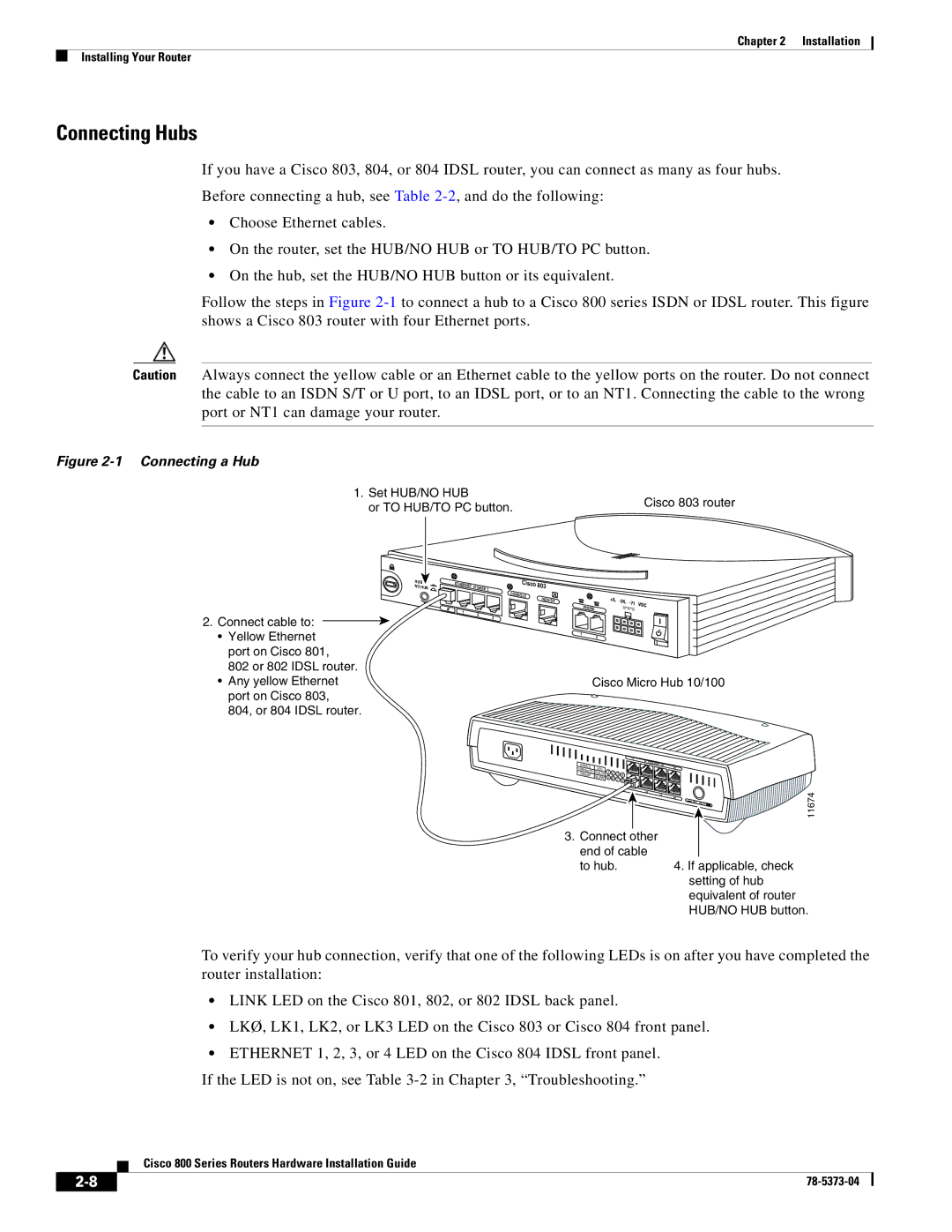
Follow the steps in Figure
Caution Always connect the yellow cable or an Ethernet cable to the yellow ports on the router. Do not connect the cable to an ISDN S/T or U port, to an IDSL port, or to an NT1. Connecting the cable to the wrong port or NT1 can damage your router.
Figure 2-1 Connecting a Hub
1. Set HUB/NO HUB | Cisco 803 router | |
or TO HUB/TO PC button. | ||
|
2.Connect cable to: ![]()
•Yellow Ethernet port on Cisco 801, 802 or 802 IDSL router.
•Any yellow Ethernet port on Cisco 803, 804, or 804 IDSL router.
HUB | ETHERNET 10 |
| Cisco | 803 | |
NO | HUB | BASE T | |||
|
| CONSOLE |
|
| ISDN S/T |
0 | 1 | PHONE |
| 2 | |
|
| 3 |
|
| 1 |
|
| 2 |
Cisco Micro Hub 10/100
|
|
|
|
| 1X |
|
SPEED |
|
|
|
| 2X | ETHERNET 3X |
LED |
|
|
|
| ||
100BaseTX | 1 |
|
|
|
| |
10BaseT | SOLID | 2 | 3 | 4 |
| |
5 | 6 |
| ||||
| BLINK | 7 | 8 |
| ||
|
|
|
|
| 6X | |
|
|
|
|
|
| 7X |
3.Connect other end of cable to hub.
4X |
|
|
|
8X |
|
| 11674 |
| MDI |
|
4.If applicable, check setting of hub equivalent of router HUB/NO HUB button.
To verify your hub connection, verify that one of the following LEDs is on after you have completed the router installation:
•LINK LED on the Cisco 801, 802, or 802 IDSL back panel.
•LKØ, LK1, LK2, or LK3 LED on the Cisco 803 or Cisco 804 front panel.
•ETHERNET 1, 2, 3, or 4 LED on the Cisco 804 IDSL front panel.
If the LED is not on, see Table
Cisco 800 Series Routers Hardware Installation Guide
| ||
|
