Port and Slot Configuration Worksheet
Port and Slot Configuration Worksheet
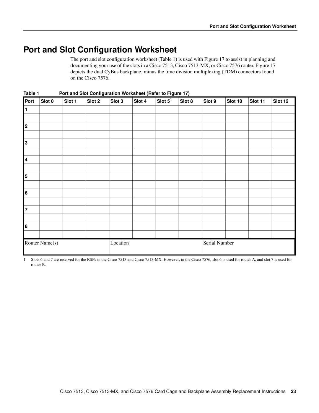
The port and slot configuration worksheet (Table 1) is used with Figure 17 to assist in planning and documenting your use of the slots in a Cisco 7513, Cisco
Table 1 | Port and Slot Configuration Worksheet (Refer to Figure 17) |
|
|
|
| |||||||
Port | Slot 0 |
| Slot 1 | Slot 2 | Slot 3 | Slot 4 | Slot 51 | Slot 8 | Slot 9 | Slot 10 | Slot 11 | Slot 12 |
1 |
|
|
|
|
|
|
|
|
|
|
|
|
|
|
|
|
|
|
|
|
|
|
|
|
|
|
|
|
|
|
|
|
|
|
|
|
|
|
2 |
|
|
|
|
|
|
|
|
|
|
|
|
|
|
|
|
|
|
|
|
|
|
|
|
|
|
|
|
|
|
|
|
|
|
|
|
|
|
3 |
|
|
|
|
|
|
|
|
|
|
|
|
|
|
|
|
|
|
|
|
|
|
|
|
|
|
|
|
|
|
|
|
|
|
|
|
|
|
4 |
|
|
|
|
|
|
|
|
|
|
|
|
|
|
|
|
|
|
|
|
|
|
|
|
|
|
|
|
|
|
|
|
|
|
|
|
|
|
5 |
|
|
|
|
|
|
|
|
|
|
|
|
|
|
|
|
|
|
|
|
|
|
|
|
|
|
|
|
|
|
|
|
|
|
|
|
|
|
6 |
|
|
|
|
|
|
|
|
|
|
|
|
|
|
|
|
|
|
|
|
|
|
|
|
|
|
|
|
|
|
|
|
|
|
|
|
|
|
7 |
|
|
|
|
|
|
|
|
|
|
|
|
|
|
|
|
|
|
|
|
|
|
|
|
|
|
|
|
|
|
|
|
|
|
|
|
|
|
8 |
|
|
|
|
|
|
|
|
|
|
|
|
|
|
|
|
|
|
|
|
|
|
|
|
|
|
|
|
|
|
|
|
|
|
|
|
|
|
Router Name(s)
Location
Serial Number
1Slots 6 and 7 are reserved for the RSPs in the Cisco 7513 and Cisco
Cisco 7513, Cisco
