Removing the Old Card Cage and Backplane Assembly
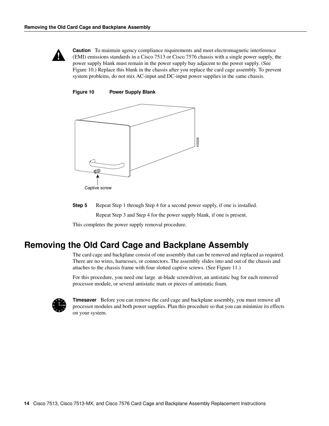
Caution To maintain agency compliance requirements and meet electromagnetic interference (EMI) emissions standards in a Cisco 7513 or Cisco 7576 chassis with a single power supply, the power supply blank must remain in the power supply bay adjacent to the power supply. (See Figure 10.) Replace this blank in the chassis after you replace the card cage assembly. To prevent system problems, do not mix
Figure 10 Power Supply Blank
H3539
Captive screw
Step 5 Repeat Step 1 through Step 4 for a second power supply, if one is installed.
Repeat Step 3 and Step 4 for the power supply blank, if one is present.
This completes the power supply removal procedure.
Removing the Old Card Cage and Backplane Assembly
The card cage and backplane consist of one assembly that can be removed and replaced as required. There are no wires, harnesses, or connectors. The assembly slides into and out of the chassis and attaches to the chassis frame with four slotted captive screws. (See Figure 11.)
For this procedure, you need one large
Timesaver Before you can remove the card cage and backplane assembly, you must remove all processor modules and both power supplies. Plan this procedure so that you can minimize its effects on your system.
14Cisco 7513, Cisco