Installing the New Card Cage and Backplane Assembly
Figure 13
Chassis interface board B
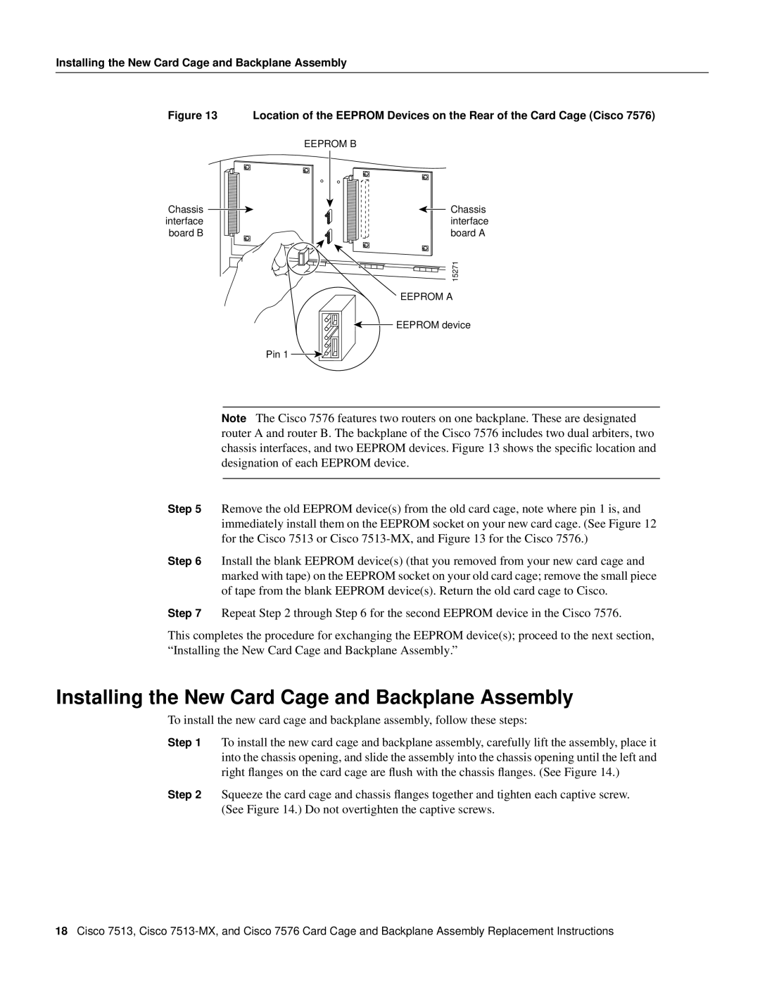
Location of the EEPROM Devices on the Rear of the Card Cage (Cisco 7576)
EEPROM B
Chassis interface board A
15271
EEPROM A
![]() EEPROM device
EEPROM device
Pin 1
Note The Cisco 7576 features two routers on one backplane. These are designated router A and router B. The backplane of the Cisco 7576 includes two dual arbiters, two chassis interfaces, and two EEPROM devices. Figure 13 shows the specific location and designation of each EEPROM device.
Step 5 Remove the old EEPROM device(s) from the old card cage, note where pin 1 is, and immediately install them on the EEPROM socket on your new card cage. (See Figure 12 for the Cisco 7513 or Cisco
Step 6 Install the blank EEPROM device(s) (that you removed from your new card cage and marked with tape) on the EEPROM socket on your old card cage; remove the small piece of tape from the blank EEPROM device(s). Return the old card cage to Cisco.
Step 7 Repeat Step 2 through Step 6 for the second EEPROM device in the Cisco 7576.
This completes the procedure for exchanging the EEPROM device(s); proceed to the next section, “Installing the New Card Cage and Backplane Assembly.”
Installing the New Card Cage and Backplane Assembly
To install the new card cage and backplane assembly, follow these steps:
Step 1 To install the new card cage and backplane assembly, carefully lift the assembly, place it into the chassis opening, and slide the assembly into the chassis opening until the left and right flanges on the card cage are flush with the chassis flanges. (See Figure 14.)
Step 2 Squeeze the card cage and chassis flanges together and tighten each captive screw. (See Figure 14.) Do not overtighten the captive screws.
18Cisco 7513, Cisco