Product Overview
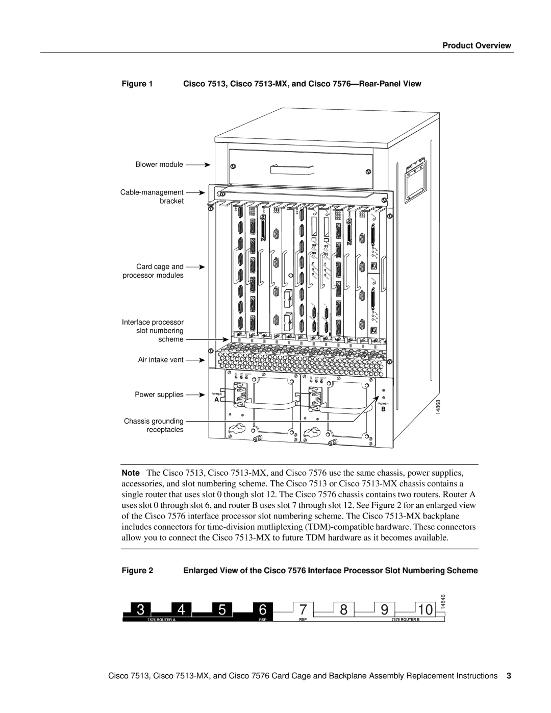
Figure 1 Cisco 7513, Cisco 7513-MX, and Cisco 7576—Rear-Panel View
Blower module ![]()
![]() bracket
bracket
Card cage and ![]() processor modules
processor modules
Interface processor slot numbering scheme
Air intake vent ![]()
AC | FAN | OUTPUT |
OK | OK | FAIL |
Power supplies | POWER |
| A |
Chassis grounding | I |
| |
receptacles | 0 |
|
NORMAL | NORMAL |
|
| |
|
|
|
| ENABLE |
EJECT | EJECT |
| ||
SLOTSLOT1 | SLOT | 1 |
| |
0 |
| SLOT0 |
| |
SLAVEMASTER | SLAVEMASTER |
| ||
SLAVE/MASTER | SLAVE/MASTER |
| ||
CPU | HALT | CPU | HALT |
|
|
|
| ||
RESET | RESET | ENABLE | ||
|
|
|
| |
AUX |
| AUX. |
|
|
. |
|
|
| |
CONSOLE | ROUTESWITCHPROCESSOR2 | CONSOLE | ROUTESWITCHPROCESSOR2 |
|
|
|
| ||
AC | FAN | OUTPUT |
OK | OK | FAIL |
POWER
B
I
0
14868
Note The Cisco 7513, Cisco
Figure 2 | Enlarged View of the Cisco 7576 Interface Processor Slot Numbering Scheme |
3 ![]() 4
4 ![]() 5
5
7576 ROUTER A
6
RSP
7
RSP
![]() 8
8 ![]() 9
9 ![]() 10
10
7576 ROUTER B
14846
Cisco 7513, Cisco