Installing the New Card Cage and Backplane Assembly
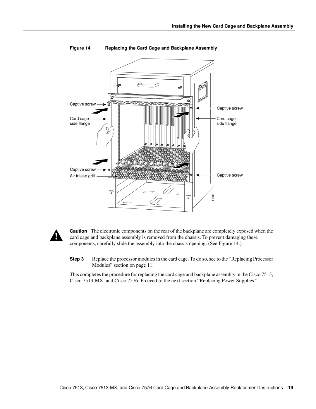
Figure 14 Replacing the Card Cage and Backplane Assembly
Captive screw ![]()
![]()
Card cage ![]() side flange
side flange
Captive screw ![]()
![]()
Air intake grill
POWER
A
POWER B
![]() Captive screw
Captive screw
![]() Card cage side flange
Card cage side flange
![]() Captive screw
Captive screw
H8819
Caution The electronic components on the rear of the backplane are completely exposed when the card cage and backplane assembly is removed from the chassis. To prevent damaging these components, carefully slide the assembly into the chassis opening. (See Figure 14.)
Step 3 Replace the processor modules in the card cage. To do so, see to the “Replacing Processor Modules” section on page 11.
This completes the procedure for replacing the card cage and backplane assembly in the Cisco 7513, Cisco
Cisco 7513, Cisco