Product Overview
Note To provide a viewable image, slot numbers 0, 1, 2, 11, and 12 are not shown in Figure 2. The slot numbering scheme uses color coding to assist in identifying routers and CyBus assignments. Refer to the “Identifying Cisco 7576 Independent Routers and CyBuses” section in the Cisco 7500 Series Installation and Configuration Guide for detailed information on the slot numbering scheme.
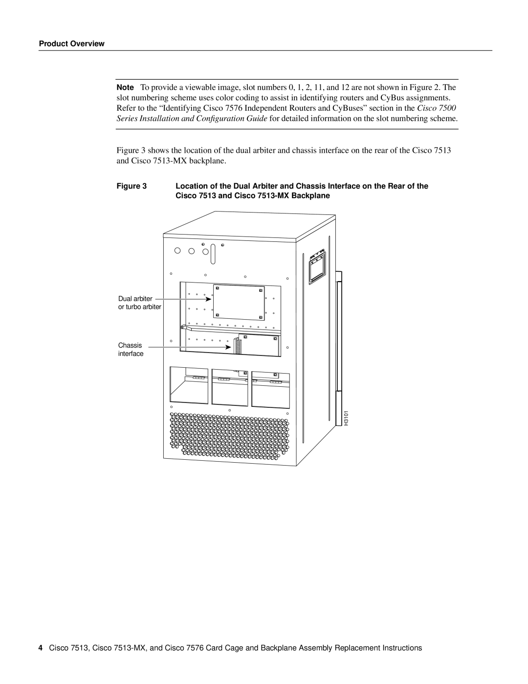
Figure 3 shows the location of the dual arbiter and chassis interface on the rear of the Cisco 7513 and Cisco 7513-MX backplane.
Figure 3 | Location of the Dual Arbiter and Chassis Interface on the Rear of the |
| Cisco 7513 and Cisco |
Dual arbiter or turbo arbiter
Chassis interface
H3101
4Cisco 7513, Cisco