Replacing Power Supplies
Replacing Power Supplies
To replace the power supply, follow these steps:
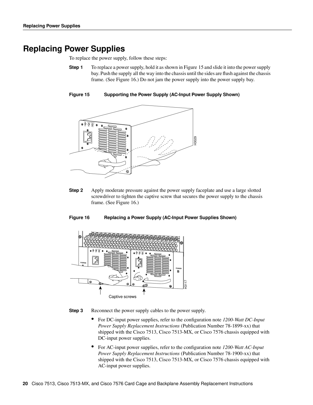
Step 1 To replace a power supply, hold it as shown in Figure 15 and slide it into the power supply bay. Push the supply all the way into the chassis until the sides are flush against the chassis frame. (See Figure 16.) Do not jam the power supply into the power supply bay.
Figure 15 Supporting the Power Supply (AC-Input Power Supply Shown)
AC | FAN OUTPUT | |
OK | OK | FAIL |
| ||
H3029
I
0
Step 2 Apply moderate pressure against the power supply faceplate and use a large slotted screwdriver to tighten the captive screw that secures the power supply to the chassis frame. (See Figure 16.)
Figure 16 Replacing a Power Supply (AC-Input Power Supplies Shown)
AC | FAN OUTPUT |
|
| |
OK | OK | AC | FAN | OUTPUT |
FAIL |
| |||
|
| OK | OK | FAIL |
POWER
A
I
I
0 0
Captive screws
POWER
B
H3117
Step 3 Reconnect the power supply cables to the power supply.
•For
•For
20Cisco 7513, Cisco