Removing Power Supplies
Caution Always install blank processor module fillers in empty processor slots to maintain the proper flow of cooling air through the chassis.
Step 7 Use a screwdriver to tighten both captive installation screws on each processor module.
Step 8 Attach network interface cables or other devices to the interface ports. Use the notes you made in the “Port and Slot Configuration Worksheet” section on page 23.
Step 9 After you reconnect power and turn it on, check the status of the interfaces as follows:
•Enter the show interfaces [type] or show controllers [type] command to verify that the system has acknowledged the interfaces and brought them up.
•Enter the configure command or the setup command facility to configure any new interface(s) you might have installed. This does not have to be done immediately, but the interfaces will not be available until you configure them.
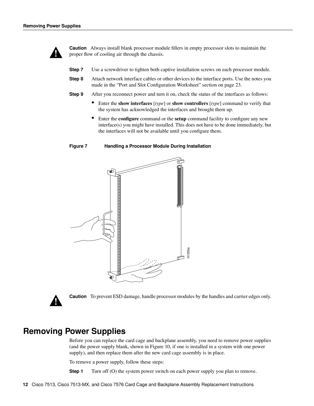
Figure 7 Handling a Processor Module During Installation
H1355a
Caution To prevent ESD damage, handle processor modules by the handles and carrier edges only.
Removing Power Supplies
Before you can replace the card cage and backplane assembly, you need to remove power supplies (and the power supply blank, shown in Figure 10, if one is installed in a system with one power supply), and then replace them after the new card cage assembly is in place.
To remove a power supply, follow these steps:
Step 1 Turn off (O) the system power switch on each power supply you plan to remove.
12Cisco 7513, Cisco