Americas Headquarters
Text Part Number OL-24002-01
Page
N T E N T S
Iii
Verifying the Sensor is Synchronized with the NTP Server
Accessories
Understanding the Power Supplies
Removing and Installing the Fan Module
Vii
Logging In to the ASA 5500 AIP SSP A-4
Viii
Obtaining and Installing the License Key Using the CLI C-11
Supported MIBs
Verifying the Master Blocking Sensor Configuration E-42
Statistics Information E-88
10/100BaseT and 10/100/1000BaseT Connectors F-1
Xiii
Xiv
Contents
Audience
Comply with Local and National Electrical Codes
Xvi
Organization
Section Title Description
Xvii
Conventions
Related Documentation
Convention Indication
Xviii
Obtaining Documentation and Submitting a Service Request
Xix
OL-24002-01
How the Sensor Functions
Capturing Network Traffic
Comprehensive Deployment Solutions
Tuning the IPS
Your Network Topology
Correctly Deploying the Sensor
Sensor Interfaces
Understanding Sensor Interfaces
For More Information
Command and Control Interface
Sensor Command and Control Interface
Sensing Interfaces
Interface Support
IPS Management 0/0
Interfaces Not
Combinations Supporting Command and Control
4GE-BP
2SX
Interfaces Not
OL-24002-01
TCP Reset Interfaces
Sensor Alternate TCP Reset Interface
Interface Restrictions
IPS Any sensing interface
Introducing the Sensor How the Sensor Functions
Interface Modes
Promiscuous Mode
IPv6, Switches, and Lack of Vacl Capture
Inline Interface Pair Mode
Set span 930, 932, 960, 962 4/1-4 both
Inline Vlan Pair Mode
3illustrates inline interface pair mode
Vlan Group Mode
Deploying Vlan Groups
Supported Sensors
Model Name Part Number Optional Interfaces Appliances
IPS-4GE-BP-INT=
IPS-2SX-INT=
IPS Appliances
Modules
Introducing the IPS Appliance
Connecting an Appliance to a Terminal Server
Config t
Appliance Restrictions
Exit Wr mem
Time Sources and the Sensor
Sensor and Time Sources
IPS Standalone Appliances
ASA IPS Modules
Verifying the Sensor is Synchronized with the NTP Server
Correcting the Time on the Sensor
Log in to the sensor
Generate the host statistics
For More Information
OL-24002-01
Preparing the Appliance for Installation
Installation Preparation
Safety Recommendations
Safety Guidelines
Electricity Safety Guidelines
Preventing Electrostatic Discharge Damage
Working in an ESD Environment
Copper foil
Preventive Site Configuration
General Site Requirements
Site Environment
Power Supply Considerations
Configuring Equipment Racks
Installing the IPS 4240 and IPS
Installation Notes and Caveats
Product Overview
Front and Back Panel Features
Indicator Description
Specifications
Indicator Color Description
Dimensions and Weight
Power
Connecting the IPS 4240 to a Cisco 7200 Series Router
Accessories
Environment
Rack Mounting
Installing the IPS 4240 and IPS
148406
Attach the network cables
Installing the IPS 4240-DC
148401
148405
For More Information
OL-24002-01
Installing the IPS
Installing the IPS Product Overview
Supported Interface Cards
4GE Bypass Interface Card
2SX Interface Card
Hardware Bypass
10GE Interface Card
Hardware Bypass Configuration Restrictions
4GE Bypass Interface Card
Hardware Bypass and Link Changes and Drops
IPS 4260 Front Panel Features
5shows the back view of the IPS
3lists the power supply indicator
4lists the specifications for the IPS
Color Description
Installing the IPS Accessories
Installing the IPS 4260 in a 4-Post Rack
153315
153317
Installing the IPS 4260 in a 2-Post Rack
153322
Installing the IPS
153309
Power on the IPS
Removing and Replacing the Chassis Cover
Sensor# reset powerdown
Installing and Removing Interface Cards
153312
Installing and Removing the Power Supply
Installing the IPS Installing and Removing the Power Supply
For More Information
OL-24002-01
Installing the IPS
Product Overview
WWW
2shows the 4GE bypass interface card
3shows the 2SX interface card
4GE Bypass Interface Card
Hardware Bypass and Link Changes and Drops
6shows the front panel switches and indicators
Front Panel Switches and Indicators
7shows the back view of the IPS
2describes the Ethernet port indicators
Indicator Indicator Green Description
Power Indicator Description Amber Green
Off Flashing AC power present Standby mode Normal
9shows the internal components
Diagnostic Panel
Indicator Component
5lists the specifications for the IPS
Installing the Rail System Kit
Understanding the Rail System Kit
Rail System Kit Contents
Space and Airflow Requirements
Installing the IPS 4270-20 in the Rack
Repeat for each chassis side rail
250221
250207
250208
250209
Repeat for each slide assembly
Extend the slide assemblies out of the rack
250212
Install the electrical cables at the back of the IPS
Extending the IPS 4270-20 from the Rack
250222
Installing the Cable Management Arm
PS1 UID Console
250215
250216
Converting the Cable Management Arm
250218
250219
250220
Installing the IPS
RJ-45 to DB-9 adapter RJ-45 to DB-9 serial cable Null-modem
Sensing
Removing and Replacing the Chassis Cover
Sensor# reset powerdown
Lift up the cover latch on the top of the chassis
Slide the chassis cover back and up to remove it
Accessing the Diagnostic Panel
Step
250204
Installing and Removing the Power Supply
PS1
Remove the power supply by pulling it away from the chassis
PCI-E x4 4
Lock the power supply handle
Installing and Removing Fans
12 Fan, Connector, and Indicator
250203
Troubleshooting Loose Connections
Installing the IPS 4345 and IPS
1lists the specifications for the IPS 4345 and the IPS
Dimensions and Weight IPS
Installing the IPS 4345 and IPS Specifications
IPS 4345 Packing Box Contents
Power button Indicators
IPS 4360 Packing Box Contents
Boot
Active
Alarm
PS0
HD1 HD2
7shows the back panel features of the IPS
3describes the rear Mgmt and network interface indicators
Rack Mount Installation
Rack-Mounting Guidelines
Installing the IPS 4345 in a Rack
Removing the Brackets from the Front of the Chassis
10 Rack-Mounting the Chassis
Installing the Appliance on the Network
Management 0/0 port RJ-45 Ethernet cable
92685
Removing and Installing the Power Supply
Understanding the Power Supplies
11 AC Power Supply and DC Power Supply
Removing and Installing the AC Power Supply
Indicator Color and State Description
12 Removing the Slot Cover
PS0PS1
Installing DC Input Power
Fixed fan Fixed DC power supply
16 IPS 4345 Back Panel
We recommend that you strip the wire to 0.27 inch 7 mm
Statement
Negative lead wire Ground lead wire Positive + lead wire
20shows the DC power supply with lead wires
Removing and Installing the DC Power Supply
Gently pull the wires out of the power supply
24 Removing the DC Power Supply
Installing the IPS 4510 and IPS
IDM
IME
PWR Boot Alarm ACT VPN PS1 PS0
HDD1 HDD2
PWR
Not supported at this time
Back panel
FAN OK
OUT Fail
Indicates status of power supply module
Off-No AC power cord connected or AC
Power switch off
Green-AC power cord connected and AC
SFP
Installing the IPS 4510 and IPS Accessories
Memory Configurations
Power Supply Module Requirements
Supported SFP/SFP+ Modules
Installing the IPS 4510 and IPS
1G SFP Module
10G SFP+ Module
Connect one RJ-45 connector to the Management 0/0 interface
Install the SFP/SFP+ module
Connect one end of the LC cable to the SFP/SFP+ module
Removing and Installing the Core IPS SSP
331818
Removing and Installing the Power Supply Module
Tighten the captive screws
Removing and Installing the Fan Module
Installing the Slide Rail Kit Hardware
Installing and Removing the Slide Rail Kit
344202
Package Contents
Installing the Chassis in the Rack
Square Studs for Square Hole Post
Securing the Slide Rail to the Rack Post
10 Installing the #10-32 Cage Nuts
11 Installing the Chassis on the Outer Rail
12 Securing the Chassis to the Outer Rail
Removing the Chassis from the Rack
Pull out the chassis to the locked position
14 Pressing Down the Release Hook
Rack-Mounting the Chassis Using the Fixed Rack Mount
331821
Reattach the power cable to the sensor Power on the sensor
331822
Installing the Cable Management Brackets
16 Cable Management Brackets for the Fixed Rack Mount
17 Cable Management Brackets for the Slide Rail
IPS 4500 Series Sensors and the SwitchApp
Installing and Removing the ASA 5500 AIP SSM
CIS
DMZ Configuration
Memory Specifications
Specification Description
Hardware and Software Requirements
Indicators
Installation and Removal Instructions
Installing the ASA 5500 AIP SSM
Color State Description
Insert the ASA 5500 AIP SSM through the slot opening
Verifying the Status of the ASA 5500 AIP SSM
Removing the ASA 5500 AIP SSM
Asa# hw-module module 1 reset
Installing and Removing the ASA 5585-X IPS SSP
Introducing the ASA 5585-X IPS SSP
ASA 5585-X SSP-10 With IPS SSP-10
1lists the specifications for the ASA 5585-X IPS SSP
ASA 5585-X SSP-20 With IPS SSP-20
ASA 5585-X SSP-40 With IPS SSP-40
ASA 5585-X SSP-60 With IPS SSP-60
Front Panel Features
1shows the front view of the IPS SSP-10 and IPS SSP-20
2shows the front view of IPS SSP-40 and IPS SSP-60
3shows the front panel indicators
PWR Boot Alarm ACT VPN PS1 PS0 HDD1 HDD2
Indicates the status of an HA pair
Green-Status of an HA pair
Indicates whether a VPN tunnel has been established
Green-VPN tunnel is established
3shows the Ethernet port indicators
Memory Requirements
Installing the ASA 5585-X IPS SSP
Power off the ASA
Remove the power cable from the ASA
SFP/SFP+ Modules
ASA 5585-X IPS SSP
Installing SFP/SFP+ Modules
Verifying the Status of the ASA 5585-X IPS SSP
Connect one end of the LC cable to the SFP/SFP+
Removing and Replacing the ASA 5585-X IPS SSP
Verify the status of the ASA 5585-X IPS SSP
ASA 5585-X IPS SSP Ejection levers
For More Information
OL-24002-01
Logging In to the Sensor
Supported User Roles
Logging In to the Appliance
Connecting an Appliance to a Terminal Server
Logging In to the ASA 5500 AIP SSP
Asa# session
Logging In to the ASA 5500-X IPS SSP
Asa# session ips
Logging In to the ASA 5585-X IPS SSP
Logging In to the Sensor
OL-24002-01
Initializing the Sensor
Understanding Initialization
Simplified Setup Mode
System Configuration Dialog
Use Http proxy server for Global Correlation?no
Basic Sensor Setup
Appendix B Initializing the Sensor Basic Sensor Setup
Appendix B Initializing the Sensor Basic Sensor Setup
Following configuration was entered
Advanced Setup
Advanced Setup for the Appliance
Enter 1 to edit the interface configuration
Enter a subinterface number and description
Enter numbers for Vlan 1
Press Enter to return to the available interfaces menu
Enter 2 to edit the virtual sensor configuration
Enter 2 to modify the virtual sensor configuration, vs0
Press Enter to return to the top-level editing menu
Enter 3 to add inline Vlan pair GigabitEthernet0/01
Host-ip 192.168.1.2/24,192.168.1.1
Enter 2 to save the configuration
Reboot the appliance
Enter yes to continue the reboot
Advanced Setup for the ASA 5500 AIP SSM
Enter 2 to modify the virtual sensor vs0 configuration
Enter a name and description for your virtual sensor
Modify default threat prevention settings?no
Reboot the ASA 5500 AIP SSM
Aip-ssm#show tls fingerprint
Advanced Setup for the ASA 5500-X IPS SSP
Enter 2 to create a signature-definition configuration file
Host-name asa-ips
Reboot the ASA 5500-X IPS SSP
Asa-ips#show tls fingerprint
Advanced Setup for the ASA 5585-X IPS SSP
Enter 2 to edit the virtual sensor configuration
Modify default threat prevention settings?no
Reboot the ASA 5585-X IPS SSP
Verifying Initialization
Ips-ssp#show tls fingerprint
View your configuration
Display the self-signed X.509 certificate needed by TLS
Sensor# show tls fingerprint
Obtaining Cisco IPS Software
Downloading Cisco IPS Software
Enter your username and password
IPS 7.1 Files
Major Update
Minor Update
Service Pack
IPS Software Versioning
Signature Update
IPS-identifier-K9-x.y-za or p1-E1.pkg
Signature Engine Update
Recovery and System Image Files
IPS Software Release Examples
Accessing IPS Documentation
Documentation is on this
Cisco Security Intelligence Operations
Obtaining a License Key From Cisco.com
Service Programs for IPS Products
Understanding Licensing
OL-24002-01
Obtaining and Installing the License Key Using the CLI
OL-24002-01
Verify the sensor is licensed
CLI
Obtaining a License for the IPS
Uninstalling the License Key
Verify the sensor key has been uninstalled
Licensing the ASA 5500-X IPS SSP
Sensor# erase license-key
MainApp 2012APR26074571468 Release
Upgrading, Downgrading, and Installing System Images
System Image Notes and Caveats
Upgrades, Downgrades, and System Images
Supported FTP and HTTP/HTTPS Servers
IPS 7.1 Upgrade Files
Upgrade Notes and Caveats
Upgrading the Sensor
Manually Upgrading the Sensor
Upgrade the sensor
Enter the password when prompted
Enter yes to complete the upgrade
Upgrading the Sensor
Verify your new sensor version
Configuring Automatic Upgrades
Upgrading the Recovery Partition
Upgrade the recovery partition
Enter the server password. The upgrade process begins
Understanding Automatic Upgrades
Automatically Upgrading the Sensor
Configuring Automatic Upgrades
Specify the username for authentication
Specify the password of the user
Verify the settings
On Cisco.com. Continue with Step
Exit automatic upgrade submode
Downgrading the Sensor
Press Enter to apply the changes or type no to discard them
Recovering the Application Partition
Recovering the Application Partition Image
Recover the application partition image
Sensorconfig# recover application-partition
Installing System Images
Rommon
Tftp Servers
Installing the IPS 4270-20 System Image
Rommon
Installing the IPS 4345 and IPS 4360 System Images
Download and install the system image
Boot IPS
IMAGE= CONFIG=
Assign the Tftp server IP address
Rommon IMAGE=systemimages/IPS-4345-K9-sys-1.1-a-7.1-3-E4.img
Installing the IPS 4510 and IPS 4520 System Image
If necessary, assign the Tftp server IP address
Installing the ASA 5500-X IPS SSP System Image
Periodically check the recovery until it is complete
Asa enable
Asa# sw-module module ips recover boot
Image the ASA 5500-X IPS SSP
Installing the ASA 5585-X IPS SSP System Image
Configure the recovery settings for the ASA 5585-X IPS SSP
Specify the default gateway of the ASA 5585-X IPS SSP
Specify the Tftp URL for the software image
Example
Installing the ASA 5585-X IPS SSP System Image Using Rommon
Boot the ASA 5585-X IPS SSP
Cisco Systems
If necessary, assign the Tftp server IP address
For More Information
Troubleshooting
Preventive Maintenance
Understanding Preventive Maintenance
Creating and Using a Backup Configuration File
Sensor# copy current-config backup-config
Sensor# more backup-config
Sensor# copy /erase backup-config current-config
Backing Up the Current Configuration to a Remote Server
Restoring the Current Configuration From a Backup File
Creating the Service Account
Exit configuration mode
Sensorconfig# user username privilege service
Disaster Recovery
Appendix E Troubleshooting Disaster Recovery
Recovering the Password
Understanding Password Recovery
Platform Description Recovery Method
ASA 5500-X IPS SSP
Recovering the Password for the Appliance
Using the Grub Menu
Using Rommon
Recovering the ASA 5500-X IPS SSP Password
Enter the following commands to reset the password
Confreg 0x7 boot
Sample Rommon session
Enter your new password twice
Session to the ASA 5500-X IPS SSP
Recovering the ASA 5585-X IPS SSP Password
Using the Asdm
Asa# hw-module module 1 password-reset
Session to the ASA 5585-X IPS SSP
Disabling Password Recovery
Verifying the State of Password Recovery
Disabling Password Recovery Using the CLI
Disabling Password Recovery Using
Troubleshooting Password Recovery
Sensorconfig-hos#show settings include password
Time Sources and the Sensor
Synchronizing IPS Module Clocks with Parent Device Clocks
Advantages and Restrictions of Virtualization
Correcting Time on the Sensor
CISCO-ENHANCED-MEMPOOL-MIB CISCO-ENTITY-ALARM-MIB
Supported MIBs
CISCO-CIDS-MIB
When to Disable Anomaly Detection
Troubleshooting Global Correlation
Disable anomaly detection operational mode
Exit analysis engine submode
Analysis Engine Not Responding
Analysis Engine is not running
Resolved
Sensor# show version
Troubleshooting External Product Interfaces
External Product Interfaces Issues
Troubleshooting the Appliance
External Product Interfaces Troubleshooting Tips
You can configure a maximum of two external product devices
Troubleshooting Loose Connections
Appliance and Jumbo Packet Frame Size
Communication Problems
Analysis Engine is Busy
Sensor# show statistics virtual-sensor
Cannot Access the Sensor CLI Through Telnet or SSH
More
Correcting a Misconfigured Access List
Sensor# show configuration include access-list
Duplicate IP Address Shuts Interface Down
Total Transmit Fifo Overruns = 0 sensor#
SensorApp and Alerting
SensorApp Is Not Running
Physical Connectivity, SPAN, or Vacl Port Issue
Sensor# show interfaces
OL-24002-01
Make sure you have Produce Alert configured
Unable to See Alerts
Sensor Not Seeing Packets
Check for alerts
Sensor# show interfaces FastEthernet0/1
Sensor# show interfaces GigabitEthernet0/1
Sensor# configure terminal sensorconfig# service interface
Check to see that the interface is up and receiving packets
Cleaning Up a Corrupted SensorApp Configuration
Replace the virtual sensor file
Remove the cache files
Troubleshooting Blocking
Blocking
Verifying ARC is Running
Verify that the MainApp is running
If the ARC is not connecting, look for recurring errors
Make sure you have the latest software updates
Sensor# show events error hhmmss month day year include nac
Sensor# show events error 000000 Apr 01 2011 include nac
For More Information
Device Access Issues
Sensor config# service network-access
Verify the IP address for the managed devices
Sensorconfig# service network-access
Router
Enter ARC general submode
Start the manual block of the bogus host IP address
Enable SSH-3DES
Type yes when prompted to accept the device
Blocking Not Occurring for a Signature
Enabling SSH Connections to the Network Device
Verifying the Master Blocking Sensor Configuration
Exit signature definition submode
Exit network access general submode
Enable debug logging for all zones
Logging
Enabling Debug Logging
Turn on individual zone control
Exit master zone control
View the zone names
Sensorconfig-log#zone-control nac severity debug
Turn on debugging for a particular zone
Exit the logger submode
Press Enter to apply changes or type no to discard them
To learn more about the IPS Logger service, refer to Logger
Zone Names
Table E-2lists the debug logger zone names
Zone Name Description
Directing cidLog Messages to SysLog
TCP Reset Not Occurring for a Signature
Sensor# show events alert
Software Upgrades
Upgrading and Analysis Engine
Which Updates to Apply and Their Prerequisites
Issues With Automatic Update
Updating a Sensor with the Update Stored on the Sensor
Troubleshooting the IDM
Cannot Launch IDM Loading Java Applet Failed
Cannot Launch the IDM-the Analysis Engine Busy
Delete the temp files and clear the history in the browser
Troubleshooting the IME
Signatures Not Producing Alerts
Troubleshooting the ASA 5500 AIP SSM
Not Supported Error Message
Time Synchronization on the IME and the Sensor
Reset
Health and Status Information
Show module
Asaconfig# hw-module module 1 recover configure
Failover Scenarios
ASA 5500 AIP SSM and the Normalizer Engine
ASA 5500 AIP SSM and the Data Plane
ASA 5500 AIP SSM and Jumbo Packet Frame Size
ASA 5500 AIP SSM and Jumbo Packets
Troubleshooting the ASA 5500-X IPS SSP
Single ASA 5500-X in Fail-Open Mode
Single ASA 5500-X in Fail-Close Mode
Two ASA 5500-Xs in Fail-Open Mode
Two ASA 5500-Xs in Fail-Close Mode
Asa# show module ips details
Asa-ips#debug module-boot
Appendix E
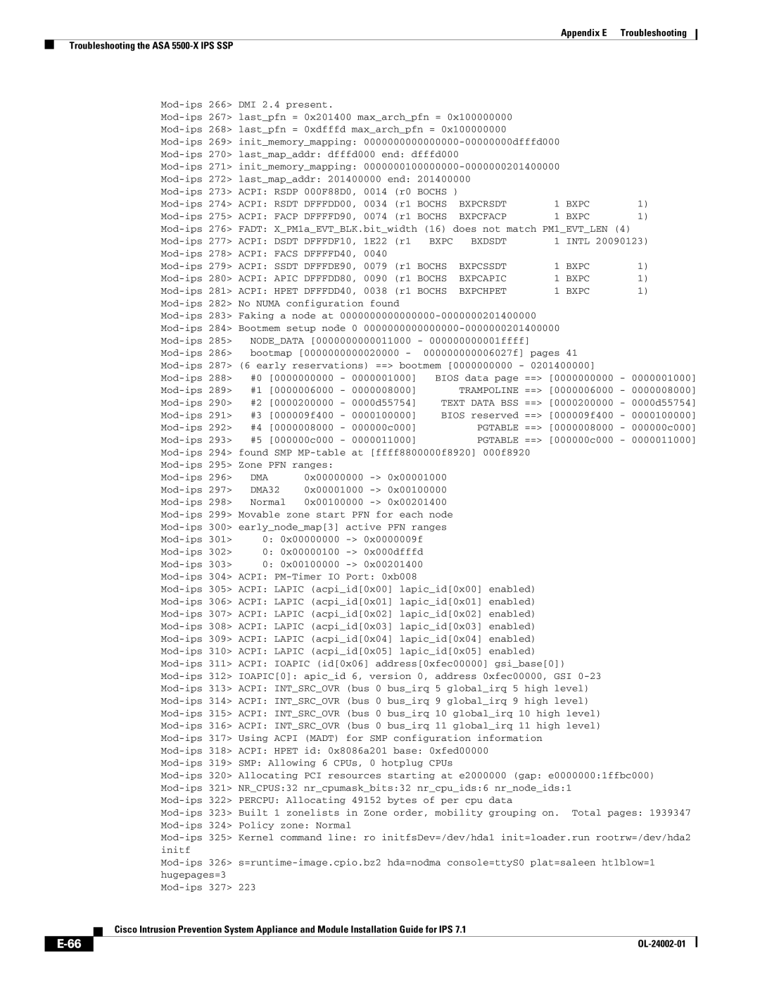
Mod-ips 351 Freeing SMP alternatives 29k freed
Mod-ips 384 CPU L2 cache 4096K
CRS
Legacy
IRQ
ASA 5500-X IPS SSP and the Normalizer Engine
ASA 5500-X IPS SSP and Memory Usage
ASA 5500-X IPS SSP and Jumbo Packet Frame Size
ASA 5500-X IPS SSP and Jumbo Packets
Platform Yellow Red Memory Used
Troubleshooting the ASA 5585-X IPS SSP
Single ASA 5585-X in Fail-Open Mode
Single ASA 5585-X in Fail-Close Mode
Two ASA 5585-Xs in Fail-Open Mode
Two ASA 5585-Xs in Fail-Close Mode
Traffic Flow Stopped on IPS Switchports
ABC1234DEFG
App. Status
Ips-ssp#hw-module module 1 recover configure
Asaconfig# debug module-boot
ASA 5585-X IPS SSP and the Normalizer Engine
Gathering Information
ASA 5585-X IPS SSP and Jumbo Packet Frame Size
ASA 5585-X IPS SSP and Jumbo Packets
Health and Network Security Information
This section contains the following topics
Show the health and security status of the sensor
Sensor# show health
Understanding the show tech-support Command
Tech Support Information
Displaying Tech Support Information
Displaying Tech Support Information
Tech Support Command Output
Sensor# show tech-support destination-url destinationurl
Sensor# show tech-support page System Status Report
Default Vlan = InlineMode = Unpaired
Version Information
Understanding the show version Command
Displaying Version Information
View version information
Cancel the output and get back to the CLI prompt
View configuration information
Sensor# more current-config
Understanding the show statistics Command
Statistics Information
Displaying Statistics
Transaction Source Virtual Sensor Web Server
Display the statistics for the Analysis Engine
Sensor# show statistics analysis-engine
Msrpctcp Msrpcudp
Display the statistics for anomaly detection
Display the statistics for authentication
Display the statistics for the Event Server
Display the statistics for the Event Store
Display the statistics for global correlation
Display the statistics for the host
Show statistics host
Sensor# show statistics network-access
Display the statistics for the logging application
Display the statistics for the ARC
Sensor# show statistics logger
Type = PIX
Display the statistics for the notification application
Display the statistics for OS identification
Display the statistics for the Sdee server
Display the statistics for the transaction server
Display the statistics for a virtual sensor
Sensor# show statistics transaction-server General
Packets Modified = Dropped
Display the statistics for the web server
Sensor# show statistics web-server listener-443
Sensor# show statistics logger clear
Understanding the show interfaces Command
Interfaces Information
100
Interfaces Command Output
Events Information
101
Understanding the show events Command
Sensor Events
Displaying Events
102
Displaying Events
103
Display alerts from the past 45 seconds
Display events that began 30 seconds in the past
104
Clearing Events
CidDump Script
Enter yes to clear the events
105
Uploading and Accessing Files on the Cisco FTP Site
Enter the following command
106
Usr/cids/idsRoot/bin/cidDump
10/100BaseT and 10/100/1000BaseT Connectors
Figure F-1shows the 10/100BaseT RJ-45 port pinouts
Console Port RJ-45
Figure F-2shows the 10/100/1000BaseT RJ-45 port pinouts
Signal Console Port RJ-45 Pin DB-9 Pin
RJ-45 to DB-9 or DB-25
Pin
OL-24002-01
Method for access control in Cisco devices
Can configure the sensor to manage ACLs
Event occurred for example, the receipt of a message
GL-1
To detect worm-infected hosts
GL-2
GL-3
Certificate for one CA issued by another CA
GL-4
GL-5
Communication networks
To legitimate users
Addresses
GL-6
Than an algorithm
Dual In-line Memory Modules
A public outside network
GL-7
GL-8
Procedures, and basic data transport methods
An ITU standard that governs H.245 endpoint control
GL-9
GL-10
Through network traffic analysis techniques
Tcpdump
GL-11
GL-12
GL-13
GL-14
GL-15
GL-16
GL-17
Types of security devices
Accepts requests for events from remote clients
TCP application
GL-18
GL-19
GL-20
Local system. Telnet is defined in RFC
GL-21
GL-22
GL-23
At the IP level
GL-24
Payload reassembly
Hosts
GL-25
GL-26
Span
IN-1
Applying software updates
ARC
ASA 5500 AIP SSM
IN-2
Converting Copy backup-config Copy current-config
URL
IPS 4270-20 Clearing Events
IN-3
Show events
Show health Show module 1 details
IN-4
Examples ASA failover configuration
Span configuration for IPv6 support
Types E-102 Event Store Clearing
Clearing events 1-24,E-16 No alerts Time stamp
IDM
IME
ASA 5500 AIP SSM ASA 5500-X IPS SSP ASA 5585-X IPS SSP
ASA 5500-X IPS SSP ASA 5585-X IPS SSP
ASA 5500 AIP SSM ASA 5585-X IPS SSP
Intrusion Prevention System Manager Express. See
IME IPS
IN-7
IN-8
Fan supply modules Not supported Power supply modules
OIR
SFP/SFP+
IN-9
SwitchApp Two power supply modules
Supported SFP modules
IN-10
SSH
IDS
IN-11
Password recovery Appliances
IN-12
Asdm
Rommon ASA 5585-X IPS SSP
IN-13
RTT
IN-14
Show statistics virtual-sensor command
Appliances Port issues Specifications
With hardware bypass
IN-15
TAC
Unix
IN-16
Show interfaces command
Sensor loose connections
Tips
IN-17
IN-18