Preparing for Installation, page Verifying Switch Operation, page
Preparing for Installation
Mounting the Switch, page
Installing a Cover for the Reset Button Optional, page
Warning Class 1 laser product. Statement
Warning No user-serviceable parts inside. Do not open. Statement
Installation Guidelines
Powering the Switch
Box Contents
Equipment That You Supply
Mounting the Switch
Verifying Switch Operation
On a Desk or Shelf without Mounting Screws
Desk, Shelf, or Wall with Mounting Screws With a Mounting Tray
On a Desk or Shelf without Mounting Screws
Desk, Shelf, or Wall with Mounting Screws
Desk- or Shelf-Mounting
Screw template 3 Desk or shelf Screws
Under the Desk- or Shelf-Mounting
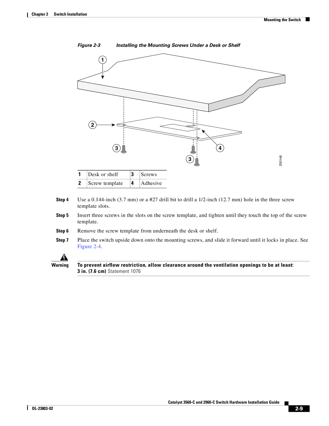
Figure 2-3 Installing the Mounting Screws Under a Desk or Shelf
2-10
Wall-Mounting
Desk or shelf
Slides on this way
Step 3 Peel the adhesive strip off the bottom of the screw template
2-11
Figure 2-6 Installing the Mounting Screws on the Wall
2-12
Figure 2-7 Installing the Switch on a Wall
Chapter 2 Switch Installation Mounting the Switch
With a Mounting Tray
Mounting Tray with Screws
2-13
2-14
Figure 2-9 Installing the Switch on the Mounting Tray
ONSOLE
Mounting Tray with a Magnet
2-15
Figure 2-10 Securing the Mounting Tray to the Switch
2-16
Figure 2-11 Placing the Switch on the Mounting Tray
Figure 2-12 Securing the Mounting Tray to the Switch
Figure 2-13 Wall-Mounting with a Magnet
2-17
Attaching Brackets to the Switch, page
Attaching Brackets to the Switch
Mounting the Switch in a Rack, page
In a Rack
2-19
Mounting the Switch in a Rack
Figure 2-16 Mounting the Switch in a Rack
Figure 2-15 Attaching the 23-inch Brackets for Rack-Mounting
Attaching the DIN-Mount Tray to the Switch, page
Attaching the DIN-Mount Tray to the Switch
Mounting the Switch on a DIN Rail, page
Removing the Switch from a DIN Rail, page
Mounting the Switch on a DIN Rail
2-21
Figure 2-18 Securing the DIN-Mount Tray to the Switch
Figure 2-19 Mounting the Switch on a DIN Rail
2-22
Removing the Switch from a DIN Rail
2-23
Switch Removal
2-24
Installing a Cover for the Reset Button Optional
Figure 2-21 Reset Cover on the Catalyst 2960CPD-8PT-L Switch
Figure 2-22 Reset Cover on the Catalyst 2960CG-8PC-S Switch
2-25
Installing the Power Cord Retainer Optional
2-26
Figure 2-24 Sliding the Retainer Through the Latch
Figure 2-25 Locking the Retainer
Figure 2-26 Sleeve Around the Power Cord
2-27
Figure 2-27 Securing the Power Cord in the Retainer
Chapter 2 Switch Installation
2-28
Installing the Cable Guard Optional
Figure 2-29 Attaching the Cable Guard to the Switch
2-29
Figure 2-30 Pivoting the Cable Guard Upwards
Catalyst
2-30
Figure 2-31 Attaching the Cables to the Switch
Figure 2-32 Guiding the Cables through the Guard
Installing SFP Modules
After Installing the Switch
2-31
Figure 2-33 Securing the Cable Guard to the Desk
Removing SFP Modules
2-32
Warning Class 1 laser product. Statement
Connecting to the 10/100 and 10/100/1000 Ports
Connecting Devices to the Ethernet Ports
Connecting to the 10/100 and 10/100/1000 Ports, page
Connecting to the PoE Ports, page
Device
Connecting to the PoE Ports
Crossover Cable
2-34
2-35
Where to Go Next
Chapter 2 Switch Installation Where to Go Next
2-36
Catalyst 3560-C and 2960-C Switch Hardware Installation Guide
OL-23803-02